
User`s guide


CARROLL TOUCH Chapter 5 - Testing Touch System Hardware and Software
Touch System Diagnostics (CTDIAG) User’s Guide 5-3
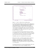
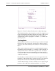
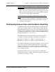
Figure 5-1. Touch Coordinates Screen (Scan Reporting)
To verify that the physical beams are working correctly, simply place a
stylus on the touch screen. This interrupts the beams and highlights the
corresponding grid boxes, indicating which beams have been
interrupted. For example, if you place a stylus in the middle of the
screen, the grid boxes in the middle of the x-axis (around 30) and the
y-axis (around 23) will highlight. At times more than one grid box per
axis is highlighted, since a finger is generally wide enough to break
more than one beam on each axis.
As you move the stylus randomly around the touch screen, the grid
boxes highlight as the corresponding beams are interrupted, and return
to normal once the stylus moves out of the beam. If you place multiple
styli on the touch screen, all beam interruptions are indicated.
Touch Mode options are not available under scan reporting.
The
Beam Trap Mode
is an additional graphic indicator. If the
Beam
Trap Mode
is on, the grid box of an interrupted beam remains
highlighted, rather than turning off, even after a stylus no longer
interrupts the beam. This creates a “permanent” record of all beam
interruptions, until you toggle the beam trap off. Toggle the beam trap
on or off by typing B.
To check the entire grid, move a stylus along the perimeter of the touch
screen, making sure that each grid box highlights when the