
User`s guide


Chapter 4 - Setting Communication Parameters CARROLL TOUCH
4-4 Touch System Diagnostics (CTDIAG) User’s Guide
On infrared systems, the default CTDIAG parity is autoparity; on guided
wave systems, it is even.
The controller parity must match the CTDIAG parity. See the RS-232
controller installation instructions for details on configuring the jumper
switch blocks. If the controller is configured to use autoparity, CTDIAG
can communicate with the touch system at all parity settings. If the
controller is set to a specific parity rather than autoparity, CTDIAG and
the controller must be set to the same parity.
HBC Communication Parameters
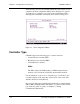
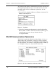
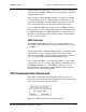
The HBC Communication Parameters Menu (Figure 4-3) lets you
define another value for the HBC I/O address or HBC interrupt. Type
the mnemonic (underlined letter) for the new value you need.
Figure 4-3. HBC Communication Parameters Menu
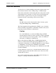
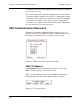
HBC I/O Address
The I/O address defines the hardware base address location of an
HBC’s hardware registers on the controller card.
When you select HBC I/O Address from the HBC Communication
Parameters Menu, the I/O Address Menu (Figure 4-4) appears.
Figure 4-4. I/O Address Menu