Touch System Diagnostics (CTDIAG) User’s Guide
Touch System Diagnostics (CTDIAG) User’s Guide an AMP company April 1998 Part #: 2950-0012-3.
Copyright Copyright ©1998 Carroll Touch. All rights reserved. Trademarks Smart-Frame is a trademark of Carroll Touch. IBM, PC, XT, AT, and PS/2 are trademarks of International Business Machines Corporation. MS-DOS, Windows, Windows 95 and Windows NT are either registered trademarks or trademarks of Microsoft Corporation. All other brands and product names are trademarks of their respective owners. Disclaimer Carroll Touch has a policy of continually improving products as new technology becomes available.
CARROLL TOUCH Table of Contents Table of Contents Welcome . . . . . . . . . . . . . . . . . . . . . . . . . . . . . . . . . . . . . v Purpose . . . . . . . . . . . . . . . . . . . . . . . . . . . . . . . . . . . . . . . . . v Audience . . . . . . . . . . . . . . . . . . . . . . . . . . . . . . . . . . . . . . . vi Organization . . . . . . . . . . . . . . . . . . . . . . . . . . . . . . . . . . . . vi Conventions . . . . . . . . . . . . . . . . . . . . . . . . . . . . . . . . . . . . . vii 1.
Table of Contents CARROLL TOUCH 5. Testing Touch System Hardware and Software . 5-1 Testing Hardware with Scan Reporting. . . . . . . . . . . . . . . Using Scan Reporting . . . . . . . . . . . . . . . . . . . . . . . . . Troubleshooting. . . . . . . . . . . . . . . . . . . . . . . . . . . . . . Testing Software with Coordinate Reporting . . . . . . . . . . Using Coordinate Reporting . . . . . . . . . . . . . . . . . . . . Tracking Mode . . . . . . . . . . . . . . . . . . . . . . . . . . .
CARROLL TOUCH Table of Contents A. Error Messages . . . . . . . . . . . . . . . . . . . . . . . . . . . A-1 B. The CTDIAG.CFG File . . . . . . . . . . . . . . . . . . . . . B-1 Autodetection and the CTDIAG.CFG File . . . . . . . . . . . . B-2 CTDIAG.CFG File Entry Definitions . . . . . . . . . . . . . . . . B-3 Entry Types . . . . . . . . . . . . . . . . . . . . . . . . . . . . . . . . . B-3 Definition of Items. . . . . . . . . . . . . . . . . . . . . . . . . . . . B-4 Serial (RS-232 Entry) . . . . . . .
Table of Contents CARROLL TOUCH List of Tables Table 2-1. CTDIAG Files . . . . . . . . . . . . . . . . . . . . . . . . . . . . . . . 2-2 Table A-1. Error Messages . . . . . . . . . . . . . . . . . . . . . . . . . . . . . . A-2 Table B-1. Example of CTDIAG.CFG File . . . . . . . . . . . . . . . . . B-2 Table B-2. Example of Last Found Entry in CTDIAG.CFG File . . . . . . . . . . . . . . . . . . . . . . . . . . .
Welcome s computers become a part of daily life, a technology that makes them easier to use has become a necessity. Carroll Touch provides the solution through the power of touch. A Because pointing or touching is a natural means of indicating choice, touch systems are ideal for selection-based applications where easy-to-follow menus guide a user through a series of steps or choices. Touch is well accepted by the casual user because its simple, natural interface hides the complexity of computer systems.
Welcome CARROLL TOUCH Audience This guide is designed for the advanced user, programmer, or software engineer who is installing and integrating Carroll Touch touch systems with host computers or who needs to troubleshoot or debug touch systems. Organization Chapter 1, “Introduction,” gives an overview of CTDIAG, its use, and its interface. Chapter 2, “Starting CTDIAG,” contains the information you need to install the Touch System Diagnostics software.
CARROLL TOUCH Welcome Conventions For clarity, this guide uses certain conventions to visually distinguish different types of information. The conventions are: • Bold is used to emphasize a word or phrase, including definitions of important concepts. • SMALL CAPITAL LETTERS (such as SPACE or ENTER) indicate a key on the keyboard. • Courier font indicates file names, directory names, messages displayed by the computer, parameters in command lines, and information to be typed by the user.
Welcome viii CARROLL TOUCH Touch System Diagnostics (CTDIAG) User’s Guide
1 Introduction he Touch System Diagnostics software (CTDIAG) is a rich and multi-featured software package that will verify that a touch system has been installed correctly. It is also a tool that will help you diagnose and correct any problems you encounter in touch system hardware or software. T This chapter gives an overview of CTDIAG, its use, and its interface. It discusses the following topics: • Purpose. • Features. • Quick Test. • Debugging. • Using the Menus.
Chapter 1 - Introduction CARROLL TOUCH Purpose CTDIAG is a menu-driven diagnostic program that you can use to verify touch system installation, troubleshoot touch system operations, and debug. CTDIAG works with any Carroll Touch touch system that uses a hardware-based controller (HBC), a software-based controller (SBC), or an RS-232 controller.
CARROLL TOUCH Chapter 1 - Introduction • • • If you are in Windows 95, restart your computer in MS-DOS mode. If you installed Windows 95 in its own directory and kept the previous version of MS-DOS and Windows 3.x, restart your computer in the previous version of MS-DOS. If you are running under Windows NT™, reboot your computer using a DOS bootable disk. Or, if you have DOS installed in another partition, reboot your computer using that partition. Take these steps: 1.
Chapter 1 - Introduction CARROLL TOUCH If errors are reported on the System Information display, if the System Information display or the Touch Coordinates screen does not appear, or if you see Touch System Init Failed at the bottom of the screen, recheck all cable connections, reboot the computer and touch system, then retest. If your system does not work upon retest, you may need to modify the other configuration options or communication parameters.
CARROLL TOUCH Chapter 1 - Introduction Figure 1-1. Example CTDIAG Menu • The Status line summarizes the configuration and communication parameters for the touch system currently in use. In Figure 1-1, the left portion of the Status line reports a configuration of the direct interface method and a hardware-based controller. The right portion indicates the I/O address and hardware interrupt request number.
Chapter 1 - Introduction 1-6 CARROLL TOUCH Touch System Diagnostics (CTDIAG) User’s Guide
2 Starting CTDIAG his chapter contains the information you need to install the Touch System Diagnostics software. It discusses the following topics: Installing the Controller Hardware. System Requirements. CTDIAG Files. Installing CTDIAG. Starting CTDIAG. Autodetection.
Chapter 2 - Starting CTDIAG CARROLL TOUCH Installing the Controller Hardware Before using or even installing CTDIAG, you should first install the touch system hardware. Each type of Carroll Touch controller comes with its own installation instructions. Once hardware installation is complete, double-check: • • the SBC or HBC to see that the modular digital interface (MDI) cable of the touch frame is correctly connected to the touch controller.
CARROLL TOUCH Chapter 2 - Starting CTDIAG Installing CTDIAG If you are installing the Carroll Touch driver for Windows 3.1 or MS-DOS, CTDIAG is automatically installed when you install the driver. If you are installing the Carroll Touch driver for Windows95 or Windows NT, you will need to run INSTALL.EXE to install CTDIAG. See the READ ME file on your installation disk for details.
Chapter 2 - Starting CTDIAG CARROLL TOUCH Starting CTDIAG To start CTDIAG, take the following steps: 1. In DOS, change to the directory containing CTDIAG (ordinarily, this is c:\ctouch\ctdos\ctdiag). Note You must run CTDIAG directly from the DOS environment. If you are running Windows 3.x, exit to the DOS prompt. In Windows 95, restart the computer in MS-DOS mode. (Do not use the MS-DOS Prompt icon!) Under Windows NT, you must reboot into a partition containing DOS or reboot using a DOS bootable disk.
3 Configuring a Touch System he CTDIAG autodetection feature attempts to automatically determine the type of touch system installed on your computer. If autodetection fails, CTDIAG offers a series of menus that lets you define the configuration of the touch system. T This chapter discusses the following topics: • Controller Type. • Interface Method. You may also use the CTDIAG command line to set the configuration options and communication parameters, as explained in Chapter 9, “Command Line Options.
Chapter 3 - Configuring a Touch System CARROLL TOUCH If autodetection does not successfully identify the touch system on your computer, the Test Configuration Menu, shown in Figure 3-1, appears. You will need to configure your touch system, which simply means defining what combination of hardware and software is being used Figure 3-1. Test Configuration Menu Controller Type CTDIAG supports the following types of touch controllers: • Software-based controller (SBC). • Hardware-based controller (HBC).
CARROLL TOUCH Chapter 3 - Configuring a Touch System Interface Method You may choose to interact with the touch system software using one of three interface methods: direct, TAPI polling, or TAPI interrupt. Direct is the usual method of interacting with the touch system for serial and hardware-based controllers. A touch on the screen interrupts the infrared beams or guided waves; the point of interruption is then interpreted and the corresponding software action is taken.
Chapter 3 - Configuring a Touch System 3-4 CARROLL TOUCH Touch System Diagnostics (CTDIAG) User’s Guide
4 Setting Communication Parameters n occasion, you may need to change the value of one or more communication parameters when the CTDIAG defaults do not match the hardware defaults. This may occur when autodetection fails, or when you change the hardware defaults. All communication parameters may be set through a Communications Parameters menu. O This chapter discusses the following topics: • RS-232 Communication Parameters. • HBC Communication Parameters. • TAPI Communication Parameters.
Chapter 4 - Setting Communication Parameters CARROLL TOUCH The parameters that regulate communication between the controller and the computer depend upon the type of controller used in your touch system. To set any of these communication parameters, take the following steps: 1. From the Test Configuration Menu, press ENTER to display the Test Menu, shown in Figure 4-1. Figure 4-1. Test Menu 2. Select Set Communication Parameters from the Test Menu.
CARROLL TOUCH Chapter 4 - Setting Communication Parameters Baud Rate Baud rate is the speed of data transfer between the RS-232 controller and the computer. The default CTDIAG baud rate is autobaud for infrared systems and 9600 for guided wave systems. The controller baud rate must match the CTDIAG baud rate. See the RS-232 controller installation instructions for details on configuring the jumper switch blocks.
Chapter 4 - Setting Communication Parameters CARROLL TOUCH On infrared systems, the default CTDIAG parity is autoparity; on guided wave systems, it is even. The controller parity must match the CTDIAG parity. See the RS-232 controller installation instructions for details on configuring the jumper switch blocks. If the controller is configured to use autoparity, CTDIAG can communicate with the touch system at all parity settings.
CARROLL TOUCH Chapter 4 - Setting Communication Parameters Type the value for the I/O address; if the value you typed is outside the allowable range of 200H to 3F0H, an error message appears and the I/O Address Menu reappears. The I/O address at which the HBC attempts to communicate with the touch system may be set by configuring jumper switch blocks on the controller. See the HBC controller installation instructions for details. The controller I/O address must match the CTDIAG I/O address.
Chapter 4 - Setting Communication Parameters CARROLL TOUCH The default interrupt of 55H was selected because it does not conflict with any known major MS-DOS software title, but any unused software interrupt may be used. Caution Selecting a software interrupt is not a simple matter; it requires a basic understanding of programming and DOS functions.
5 Testing Touch System Hardware and Software ne of the most useful functions of CTDIAG is touch coordinate testing, which tests the touch system hardware and software. This chapter discusses the following topics: • Testing Hardware with Scan Reporting. • Testing Software with Coordinate Reporting. • Relationship between Scan and Coordinate Reporting.
Chapter 5 - Testing Touch System Hardware and Software CARROLL TOUCH Touch coordinate testing includes: • Scan reporting, which reports the results of a touch in physical beams. It is especially useful for checking hardware operations and is available for scanning infrared systems only. • Coordinate reporting, which reports the results of a touch in x, y coordinates. It is especially useful for checking software operations.
CARROLL TOUCH Chapter 5 - Testing Touch System Hardware and Software Figure 5-1. Touch Coordinates Screen (Scan Reporting) To verify that the physical beams are working correctly, simply place a stylus on the touch screen. This interrupts the beams and highlights the corresponding grid boxes, indicating which beams have been interrupted. For example, if you place a stylus in the middle of the screen, the grid boxes in the middle of the x-axis (around 30) and the y-axis (around 23) will highlight.
Chapter 5 - Testing Touch System Hardware and Software CARROLL TOUCH corresponding beam is interrupted. If Beam Trap Mode is on, all grid boxes should be highlighted at the end of the process. If a few grid boxes remain not highlighted, run the stylus through those beams again to see if they simply were not interrupted on the first pass. As an additional check, place the stylus in each corner of the screen; the grid boxes for the maximum or minimum physical beam values should highlight.
CARROLL TOUCH Chapter 5 - Testing Touch System Hardware and Software If you are using a serial (RS-232) controller or a Smart-Frame: • Check that power is supplied to the RS-232 controller or Smart-Frame. • Check that the communication cable is properly connected to the correct comm port. • Ensure that the controller or Smart-Frame jumpers (if any) are set to either autobaud or to a fixed baud rate and parity that matches those shown on the Status line.
Chapter 5 - Testing Touch System Hardware and Software CARROLL TOUCH Figure 5-2. Touch Coordinate Test Screen (Coordinate Reporting) The Touch Mode defines what is meant by a touch. For example, does a touch occur when the stylus enters the active area of the touch screen or when it leaves the active area? Select the various touch modes, as explained in the next few paragraphs, to test that x, y coordinates are reported properly.
CARROLL TOUCH Chapter 5 - Testing Touch System Hardware and Software increases as you move right and decreases as you move left and that the y coordinate increases as you move down and decreases as you move up. If a stylus is in the corner of the screen, the coordinates should reflect the maximum or minimum x, y coordinates.
Chapter 5 - Testing Touch System Hardware and Software CARROLL TOUCH If used in conjunction with Exit Point Mode, adding the modifier results in double reporting of each exit point. To add an Exit Point Modifier, type A. Troubleshooting If an error message appears in the Message line, look up the suggested actions in Appendix A, “Error Messages.
CARROLL TOUCH Chapter 5 - Testing Touch System Hardware and Software Touch Coordinates screen appears, but non-contiguous messages appear unexpectedly. • Make sure you are only interrupting the infrared beam with one finger - use a pen as a stylus to make sure. If messages persist, the frame may have failed beams. If you are using an HBC or RS-232 controller, use scan reporting to check further. Touch Coordinates screen appears, but there are dead spots on the screen.
Chapter 5 - Testing Touch System Hardware and Software 5-10 CARROLL TOUCH Touch System Diagnostics (CTDIAG) User’s Guide
6 Touch System Information A summary report of the touch system is available through CTDIAG.
Chapter 6 - Touch System Information CARROLL TOUCH To view system information for touch systems, take the following steps: 1. From the Test Configuration Menu (Figure 3-1), press ENTER to display the Test Menu. 2. Select System Info from the Test Menu (Figure 4-1). The System Information screen, shown in Figure 6-1, appears. Figure 6-1. System Information Screen This screen reports the results of various commands in the Smart-Frame Protocol. • Processor Errors identifies the current error conditions.
CARROLL TOUCH Chapter 6 - Touch System Information - • Reporting Method: Coordinate reporting or scan reporting is active. - Touch Mode: Tracking Mode, Continuous Mode, Exit Point Mode, or Enter Point Mode is active, with or without an Exit Point Modifier. - Touch Scanning: Touch system is not detecting (off) or is detecting (on) touch. - Report Transfer: Smart-Frame Protocol reports are not sent (off) or are sent (on) to the host.
Chapter 6 - Touch System Information 6-4 CARROLL TOUCH Touch System Diagnostics (CTDIAG) User’s Guide
7 Debug he Debug option lets you send and receive SFP commands and reports and directly observe the communication between the host and the touch system. This provides a simple way to check operations of the commands. T This chapter discusses the following topics: • Debug Overview. • Debug Screen. • Debug Commands and Debug Help. • Trace Buffer. • Debugging under the Smart-Frame Protocol. Caution Use of Debug requires an understanding of the complexities of the Smart-Frame Protocol.
Chapter 7 - Debug CARROLL TOUCH Debug Overview Debug allows you to observe the SFP commands sent to the touch system and the reports received from the touch system. For example, an SFP command might be a request to the touch system for the current touch coordinates and the associated report would be the actual touch coordinates. You can also use another debugger, based upon the Touch Application Program Interface (TAPI), to monitor host/touch system communication, as described in Chapter 8.
CARROLL TOUCH Chapter 7 - Debug Figure 7-1. Debug Screen Debug Commands and Debug Help A number of debug commands are available to help you with troubleshooting. To see a brief summary of these commands, press F1 for debug help (Figure 7-2). You do not have to display the Help window to use these functions; it is simply a reminder of the available commands. Figure 7-2. Debug Help Window Debug Help Window (F1 key) displays the Debug Help Window.
Chapter 7 - Debug CARROLL TOUCH The Debug screen reappears once you have made any necessary changes. For information on these parameters, see Chapter 4. View Trace Buffer (F4 key) displays the Trace Buffer screen, which contains a copy of the communications trace buffer. See the next section for more information. Clear Trace Buffer (F5 key) erases the communications trace buffer. Clear TxRx Windows (F6 key) erases the transmit and receive windows.
CARROLL TOUCH Chapter 7 - Debug To make a copy of the buffer and display it in the Trace Buffer screen (Figure 7-3), press F4. While you are viewing the copy of the trace buffer, CTDIAG continues to record any new communication in the trace buffer. This new communication will not appear in the Trace Buffer screen currently on display, since the screen is merely a static copy of the actual buffer.
Chapter 7 - Debug CARROLL TOUCH Reports An SFP report has the format: header report bytes trailer The trailer is always FF. An example of a report returned from the Get_Error_Report command is: F8 00 FF F8 is the header and 00 indicates no errors. An example of a touch coordinate report is: FE 35 2D FF FE is the header and 35 and 2D are the x, y touch coordinates. Transmit Window When you type a command number, it is echoed in the Tx window.
CARROLL TOUCH Chapter 7 - Debug 2. Press F8 to initialize the infrared touch system. (Remember, you can press F1 to see the help screen that reminds you of the commands available in debug.) 3. Press the F4 key to make a copy of the trace buffer and display it in the Trace Buffer screen. The Trace Buffer screen appears, as shown in Figure 7-3. On the monitor, commands are gray and reports are white. A string of hexadecimal commands and reports is displayed in the trace buffer.
Chapter 7 - Debug CARROLL TOUCH Figure 7-4. Debug Screen: SFP Touch Coordinates 6. Press F4 to copy the trace buffer into the Trace Buffer screen, as shown in Figure 7-5. Data in the buffer is displayed in a continuous stream. Note that the 13 sets of touch coordinates now appear in the trace buffer. Figure 7-5. Trace Buffer Screen: SFP Touch Coordinates 7. Touch the display again and move your finger around, noting that no change occurs on the Trace Buffer screen.
CARROLL TOUCH Chapter 7 - Debug 8. Press the F4 key again to copy the trace buffer into the Trace Buffer screen. There is now more data on the screen, reflecting the coordinate reports sent during the touch in step 7. 9. Press the ESC key to return to the Debug screen, then ESC again to return to the Test Menu.
Chapter 7 - Debug 7-10 CARROLL TOUCH Touch System Diagnostics (CTDIAG) User’s Guide
8 TAPI Debug Debug permits communication with a Touch Application T API Program Interface (TAPI) driver via TAPI function calls. This allows you to experiment with TAPI functions and manually verify that the TAPI driver is loaded and functioning correctly. This chapter discusses the following topics: • Loading the TAPI Driver. • Debug and TAPI Drivers. • TAPI Debug Example.
Chapter 8 - TAPI Debug CARROLL TOUCH Loading the TAPI Driver TAPI driver is a generic term that refers to the SBC driver, the HBC driver, or the serial (RS-232) driver. Each driver is a terminate-and-stayresident (TSR) program that provides a controller-independent set of function calls (the TAPI function calls) to CTDIAG. The driver communicates to a specific controller via PC bus I/O ports or an RS-232 port, depending on the type of controller.
CARROLL TOUCH Chapter 8 - TAPI Debug ltapi.bat If the driver does not install correctly, check all communication parameters, then refer to the Touch System Programmer’s Guide for additional information. 2. Start CTDIAG and use TAPI interrupt as the interface method. You can specify TAPI interrupt as a command line option (ctdiag i:T; see Chapter 9 for details) or in the CTDIAG.CFG configuration file (see Appendix B for details). The Test menu appears.
Chapter 8 - TAPI Debug CARROLL TOUCH CTDIAG loads the value 0H into the BX, CX, and DX registers, makes the function call to the TAPI driver via the TAPI software interrupt (usually 55H) and displays the returns in the registers, as shown in Figure 8-2. Figure 8-2. SFP TAPI Debug Results An AX value of 4 is the correct function call for GetCommunicationParameters.
9 Command Line Options may set configuration, communication, and autodetection Y ouparameters using the CTDIAG command line, rather than using the menus described in earlier chapters. Terminology has been explained in detail in Chapters 2, 3 and 4. This chapter discusses the following topics: • CTDIAG Command Line. • Examples.
Chapter 9 - Command Line Options CARROLL TOUCH CTDIAG Command Line The CTDIAG command line has the following syntax: ctdiag parameters If you use any command line parameters, CTDIAG skips autodetection. The available parameters follow. Note The command line is case-insensitive. Parameters may be either uppercase or lowercase, and may be arranged in any order. N = Specifies no autodetection. Annn = Specifies the I/O address. nnn may be a value from 200H to 3F0H. The default is 300H.
CARROLL TOUCH Chapter 9 - Command Line Options C:x = Specifies the controller type. x may be: C = Software-based controller. H = Hardware-based controller. R = Serial (RS-232) controller (default). Xx = Specifies the origin of the x-axis of the touch screen. x may be: L = Left side (default). R = Right side. Yx = Specifies the origin of the y-axis of the touch screen. x may be: T = Top (default). B = Bottom. Note Command line parameters are evaluated from left to right.
Chapter 9 - Command Line Options CARROLL TOUCH ctdiag N Because no other parameters are specified on the command line, default values are used. The command line equivalent of those defaults is: ctdiag I:D C:R C1 B96 PE XL YT Serial (RS-232) Controller To start CTDIAG with a serial (RS-232) controller using COM2 and a baud rate of 19200, type: ctdiag C:R C2 B19200 CTDIAG uses the defaults of even parity and direct interface method.
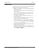
A Error Messages of the touch system problems that can be detected by M ost CTDIAG are identified through scan reporting and coordinate reporting, as explained in Chapter 5. However, CTDIAG also produces a number of error messages, which are explained in this appendix.
Appendix A - Error Messages CARROLL TOUCH Table A-1. Error Messages A-2 Message: An attempt to initialize the touch system using the command line parameters failed. Check the command line parameters for correct values. Check to insure that the touch system is installed properly. Press ‘ENTER’ to proceed to the configuration menu or press ‘ESC’ to exit. Meaning: The specified command line parameters failed to initialize the touch system.
CARROLL TOUCH Appendix A - Error Messages Table A-1. Error Messages (Continued) Message: Autodetection failed. No Touch System listed in CTDIAG.CFG was found. Check the CTDIAG.CFG file to insure your touch system is specified in an entry. Check to insure that the touch system is installed properly. Press ‘ENTER’ to proceed to the configuration menu or press ‘ESC’ to exit. Meaning: Autodetection has examined all entries in the .CFG file and has not detected any of the configurations.
Appendix A - Error Messages CARROLL TOUCH Table A-1. Error Messages (Continued) Message: Driver is not installed Meaning: The appropriate TAPI driver for the controller must be installed in order to execute. Action: Install the appropriate TAPI driver (HBC, SBC, RS-232). Message: Frame fail to respond Meaning: CTDIAG cannot communicate with the HBC or RS-232 controller or Smart-Frame.
CARROLL TOUCH Appendix A - Error Messages Table A-1. Error Messages (Continued) Message: HBC TAPI Driver Not Found at S/W Interrupt xxH Meaning: CTDIAG cannot find the HBC TAPI driver at the indicated software interrupt. Action: Install the proper TAPI driver at the desired software interrupt. Otherwise, select the proper controller interface method and/or software interrupt using the CTDIAG menus.
Appendix A - Error Messages CARROLL TOUCH Table A-1. Error Messages (Continued) A-6 Message: Invalid Report Received - Error Report Meaning: This error occurs during a request for System Information. A report was not received after issuing a Get_Error_Report command. Action: Select Debug from the Test Menu and examine the Trace history to determine more about the condition. Message: Invalid Report Received - Failed Beam Report Meaning: This error occurs during a request for System Information.
CARROLL TOUCH Appendix A - Error Messages Table A-1. Error Messages (Continued) Message: IO address is not on an 8 byte boundary*** Meaning: The selected RS-232 I/O address is not on an 8-byte boundary. Action: Change the I/O address to a correct address on an 8-byte boundary. The last digit must equal 0 or 8, such as 2F0H or 2F8H. Message: IO address is not on an 16 byte boundary*** Meaning: The selected HBC I/O address is not on a 16 byte boundary.
Appendix A - Error Messages CARROLL TOUCH Table A-1. Error Messages (Continued) A-8 Message: No VALID Comm Port Address found Meaning: CTDIAG could not find an entry in the comm port table maintained in RAM by the ROM BIOS that matched either the default COM1 I/O address of 3F8H or the default COM2 I/O address of 2F8H. Action: This error is usually associated with the use of multi-port comm boards.
CARROLL TOUCH Appendix A - Error Messages Table A-1. Error Messages (Continued) Message: The SBC controller type cannot be used with the Direct interface method Meaning: A test is attempted with the SBC and the direct interface method selected. Action: If the SBC controller is selected, the TAPI interface method must be selected. Message: Touch did not de-activate. Touch is still enabled. Meaning: An attempt was made to disable the touch using the SetTouchMode command.
Appendix A - Error Messages CARROLL TOUCH Table A-1. Error Messages (Continued) A-10 Message: Touch System Init Failed - Unable To Send Command Meaning: The system is unable to send one of the commands in the initialization process. Action: Select Debug from the Test Menu and examine the Trace history to determine more about the condition. Message: Unable to open file Meaning: CTDIAG is unable to open a DOS file in which to place a copy of the Trace buffer.
B The CTDIAG.CFG File he autodetection process uses CTDIAG.CFG, a file that contains a list of commonly used touch system configurations. Details on the CTDIAG.CFG file are given in this appendix, in the following topics: • Autodetection and the CTDIAG.CFG File. • CTDIAG.CFG File Entry Definitions.
Appendix B - The CTDIAG.CFG File CARROLL TOUCH Autodetection and the CTDIAG.CFG File To determine the type of touch system in use, CTDIAG attempts to communicate with the touch system using a list of commonly used touch system configurations, contained in the CTDIAG.CFG file. This process is known as autodetection. By default, CTDIAG.CFG is in the c:\ctouch\ctdos\ctdiag directory. Each touch system configuration in the file has a header of [SearchListEntry].
CARROLL TOUCH Appendix B - The CTDIAG.CFG File If communication is not successful, CTDIAG refers to the next [SearchListEntry] and attempts the search again. As the search progresses, messages appear indicating the configurations that were not found. If CTDIAG reaches the end of the CTDIAG.CFG file without finding a match, the message Autodetection failed appears, followed by the Test Configuration Menu.
Appendix B - The CTDIAG.CFG File CARROLL TOUCH Definition of Items To define either a[LastFound] or [SearchListEntry] entry type, use the following definition items. The default values are bolded. • Interface Method: Direct, TAPI polling, TAPI interrupt. • Controller type: HBC, serial (RS-232). • Comm port: COM1, COM2, COM3, COM4. • Baud rate: 300, 600, 1200, 2400, 4800, 9600, 19200, 38400, 115200. • Parity: None, even, odd. • I/O address: HBC address (200 - 3F0) (300H).
CARROLL TOUCH Appendix B - The CTDIAG.CFG File TAPI Entry The definition items used to specify a serial (RS-232) entry are: • Interface method. • Software interrupt. No other items are valid. Comments Comments may be used within the CTDIAG.CFG file. If the comment designator (;) is placed as the first character of a line, no translation of that line is attempted. No comment lines should be placed in the [Last Found] entry. All comment lines are preserved upon update of the CTDIAG.CFG file.
Appendix B - The CTDIAG.
CARROLL TOUCH Glossary Glossary Add Exit Point Modifier A modifier that can be added to any of the four touch reporting types (Continuous Mode, Enter Point Mode, Exit Point Mode, Tracking Mode) under the SFP and that reports the coordinates at which the stylus exits the screen. axis (x-axis, y-axis, z-axis) A dimension that makes up the touch coordinate system. The x-axis is the horizontal axis and the y-axis is the vertical axis.
Glossary CARROLL TOUCH Continuous Mode A touch reporting type under the SFP that reports touch coordinates at intervals from the time a stylus enters the screen until it exits, even if the stylus is unmoving. Add Exit Point can be added as a modifier. controller The interface between the touch system and the computer. The controller may be software-based or hardware-based, or may use the computer’s serial (RS-232) port.
CARROLL TOUCH Glossary hardware-based controller (HBC) A touch-system-independent, digital controller containing a microprocessor. The HBC is a half-card installed in the computer, drawing its power through the PC bus and communicating through the bus using an I/O address and hardware interrupt. hardware interrupt A dedicated hardware line between the touch system and the computer, defining where to search for an SBC or HBC. HBC See hardware-based controller (HBC).
Glossary CARROLL TOUCH opto-pair An infrared light-emitting diode (LED) matched with a phototransistor and set opposite one another in an infrared touch frame (opto-matrix frame) and pulsed sequentially so as to send and receive a single beam of infrared light. See beam. parity A parameter used for error-checking to ensure that the data that was transmitted by the serial peripheral is identical to that received by the computer, and vice versa.
CARROLL TOUCH Glossary software-based controller (SBC) A touch-system-independent, digital controller that has no microprocessor, but, instead, shares processor time with the host microprocessor. The SBC is a half-card installed in the computer, drawing its power through the PC bus and communicating through the bus using an I/O address and hardware interrupt.
Glossary CARROLL TOUCH touch mode A touch mode that determines when touch coordinates are reported. Enter Point Mode reports only the coordinates at which a finger or stylus enters the touch screen. Exit Point Mode reports only the coordinates at which the stylus exits the touch screen. Tracking Mode reports the coordinates of the entry of the touch screen and all movement within the screen.
CARROLL TOUCH Index Index A Add Exit Point Modifier . . . . . . . . . . . . . . . . . . . . . . . . . . . . .5-7, 6-3 ASCII format . . . . . . . . . . . . . . . . . . . . . . . . . . . . . . . . . . . . .7-4, 7-6 autobaud . . . . . . . . . . . . . . . . . . . . . . . . . . . . . . . . . . . . . 4-3, 5-5, 5-8 autodetection . . . . . . . . . . . . . . . . . . . . . . . . . . .2-2, 2-4, 3-2, 4-1, 9-2 autoparity . . . . . . . . . . . . . . . . . . . . . . . . . . . . . . . . . . . . . . . . . . .
Index CARROLL TOUCH CTDIAG command line . . . . . . . . . . . . . . . . . . . . . . . . . . . . . . . . . . . . . 2-4 files . . . . . . . . . . . . . . . . . . . . . . . . . . . . . . . . . . . . . . . . . . . . . 2-2 installation directory . . . . . . . . . . . . . . . . . . . . . . . . . . . . . . . . 2-3 overview . . . . . . . . . . . . . . . . . . . . . . . . . . . . . . . . . . . . . . . . . 1-2 starting . . . . . . . . . . . . . . . . . . . . . . . . . . . . . . . . . . . . . . . . . .
CARROLL TOUCH Index Get_Firmware_Version_Report (34H) command . . . . . . . . . . . . 6-2 Get_Frame_Size_Report (37H) command . . . . . . . . . . . . . . . . . . 6-2 Get_State_Report (47H) command . . . . . . . . . . . . . . . . . . . . . . . 6-2 guided wave systems . . . . . . . . . . . . . . . . . . . . . . . . . . . 4-3, 4-4, 5-2 guided wave technology . . . . . . . . . . . . . . . . . . . . . . . . . . . . . . . . 1-2 H hardware base address . . . . . . . . . . . . . . . . . . . . . . . . . . . . . .
Index CARROLL TOUCH M MDI cable . . . . . . . . . . . . . . . . . . . . . . . . . . . . . . . . . . . . . . . . . . . menus navigating . . . . . . . . . . . . . . . . . . . . . . . . . . . . . . . . . . . . . . . . selecting items from . . . . . . . . . . . . . . . . . . . . . . . . . . . . . . . . Message line . . . . . . . . . . . . . . . . . . . . . . . . . . . . . . . . . . . . . . . . . mnemonic . . . . . . . . . . . . . . . . . . . . . . . . . . . . . . . . . . . . . . . . . . .
CARROLL TOUCH Index software-based controller installation . . . . . . . . . . . . . . . . . . . . . . 2-2 starting CTDIAG . . . . . . . . . . . . . . . . . . . . . . . . . . . . . . . . . . . . . 2-4 State Report . . . . . . . . . . . . . . . . . . . . . . . . . . . . . . . . . . . . . . . . . 6-2 Status line . . . . . . . . . . . . . . . . . . . . . . . . . . . . . . . . . . . . . . . . . . . 1-5 stop bits . . . . . . . . . . . . . . . . . . . . . . . . . . . . . . . . . .
Index CARROLL TOUCH V View Trace Buffer command . . . . . . . . . . . . . . . . . . . . . . . . . . . . 7-4 virtual beams . . . . . . . . . . . . . . . . . . . . . . . . . . . . . . . . . . . . . . . . . 5-9 W Windows 3.x . . . . . . . . . . . . . . . . . . . . . . . . . . . . . . . . . . . . . . . . . 2-4 Windows 95 . . . . . . . . . . . . . . . . . . . . . . . . . . . . . . . . . . . . . . . . . 2-4 Windows NT . . . . . . . . . . . . . . . . . . . . . . . . . . . . . . . . . . . . . . . . .
CONTACTING CARROLL TOUCH: Carroll Touch 2800 Oakmont Drive Round Rock, Texas 78664 http://www.carrolltouch.