Touchmonitor User Guide 1528L 15-inch LCD Desktop Touchmonitor Model ET1528L
User Guide 15-inch LCD Desktop 1528L Touchmonitor Revision B P/N E894354 ii
Copyright 2008 Tyco Electronics Corporation. All Rights Reserved. No part of this publication may be reproduced, transmitted, transcribed, stored in a retrieval system, or translated into any language or computer language, in any form or by any means, including, but not limited to, electronic, magnetic, optical, chemical, manual, or otherwise without prior written permission of Tyco Electronics Corporation. Disclaimer The information in this document is subject to change without notice.
Warnings and Cautions Warning • Danger — Explosion hazard. Do not use in the presence of flammable anesthetics. • To prevent fire or shock hazards, do not immerse the unit in water or expose it to rain or moisture. • Do not use the unit with an extension cord receptacle or other outlets unless the prongs of the power cord can be fully inserted. • RISK OF ELECTRICAL SHOCK — DO NOT OPEN. To reduce the risk of electrical shock, DO NOT remove the back of the equipment or open the enclosure.
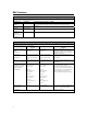
EMC Guidance Guidance and manufacturer’s declaration – electromagnetic emissions The 1528L is intended for use in the electromagnetic environment specified below. The customer or the user of the 1528L should assure that it is used in such an environment. Emissions test Compliance Electromagnetic environment – guidance RF emissions Group 1 The 1528L uses RF energy only for its internal function.
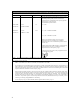
Guidance and manufacture’s declaration – electromagnetic immunity The 1528L is intended for use in the electromagnetic environment specified below. The customer or the user of the 1528L should assure that it is used in such an environment.
Recommended separation distances between Portable and mobile RF communications equipment and the 1528L The 1528L is intended for use in which radiated RF disturbances are controlled. The customer or the user of the 1528L can help prevent electromagnetic interference by maintaining a minimum distance between portable and mobile RF communications equipment (transmitters) and the 1528L as recommended below, according to the maximum output power of the communications equipment.
Classification With respect to electrical shock, fire in accordance with UL60601-1 and CAN/CSA C22.2 No. 60601-1 This monitor is a CLASS 1 (GROUNDED) DEVICE. This monitor is classified NO APPLIED PARTS EQUIPMENT. Protection against harmful ingress of water: INGRESS PROTECTION (IPX1) This monitor shall be classified as ORDINARY EQUIPMENT, not intended or evaluated for use in the presence of flammable anesthetic mixture with air, oxygen, or nitrous oxide. Mode of Operation: CONTINUOUS OPERATION.
Table of Contents Warnings and Cautions.................................................................................. iv EMC Guidance................................................................................................................ v Classification................................................................................................................ viii INTRODUCTION .......................................................................................... 3 Product Description .
Type .......................................................................................................................... 22 H. Scan (KHz)........................................................................................................... 22 V. Scan (Hz).............................................................................................................. 22 Polarity......................................................................................................................
CHAPTER INTRODUCTION Product Description The 1528L is a medical 15-inch touchmonitor which uses liquid crystal monitor (LCD) technology, designed to present information to the operator, care-giver and the patient. The 1528L features both serial and USB touch interfaces as standard configuration. The 1528L functionally consists of a 15-inch LCD main monitor with a touchscreen. The monitor element is a 15.0 inch diagonal XGA resolution (1024x768) LCD monitor.
External Medical Grade Power Adapter The 1528L is powered by an external medical grade universal input power adapter.
CHAPTER INSTALLATION AND SETUP This chapter discusses how to install your LCD touchmonitor and how to install Elo TouchSystems driver software.
Product Overview Front View Rear View 6
Side View Kensington™ Lock The Kensington™ lock is a security device that prevents theft. To find out more about this security device, go to http://www.kensington.com. USB Interface Connection Your touchmonitor comes with one USB cable. (For use with Windows 2000, ME, and XP systems only.
Remove the Cable Cover The cables are connected at the back of the monitor. CAUTION Before connecting the cables to your touchmonitor and PC, be sure that the computer and touchmonitor are turned off. To remove the cable cover, place your thumbs at the top corners of the cable cover where the indents are (above the arrows). Gently press and pull the cover toward yourself.
Connect one end of the video cable to the rear side of computer and the other to the LCD. Tighten by turning the two thumb screws clockwise to ensure proper grounding. You can select D-SUB15 video cable or DVI video cable, shown respectively. Connect one end of the speaker cable to the speaker port in the computer and the other end to the port in the monitor. or Connect one end of the Serial or USB cable to the rear side of the computer and the other to the LCD monitor, shown respectively.
Replace the Cable Cover After you have attached all the cables to the monitor; gently bring all the cables toward the center so they fit under the cable cover lip. Snap the cable cover in place over the connections. Optimizing the LCD Monitor To ensure the LCD monitor works well with your computer, configure the monitor mode of your graphic card to make it less than or equal to 1024 x 768 resolution, and make sure the timing of the monitor mode is compatible with the LCD monitor.
Additional drivers and driver information for other operating systems (including Macintosh and Linux) are available on the Elo TouchSystems web site at www.elotouch.com. Your Elo USB touchmonitor is “plug-and-play” compliant. Information on the video capabilities of your touchmonitor is sent to your video monitor adapter when Windows starts. If Windows detects your touchmonitor, follow the instructions on the screen to install a generic plug-and-play monitor.
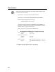
4. Follow the directions on the screen to complete the driver setup for your version of Windows.
CHAPTER OPERATION About Touchmonitor Adjustments Your touchmonitor will unlikely require adjustment. Variations in video output and application may require adjustments to your touchmonitor to optimize the quality of the display. For best performance, your touchmonitor should be operating in native resolution, that is 1024x768 at 60-75 Hz. Use the Display control panel in Windows to choose 1024x768 resolution. Operating in other resolutions will degrade video performance.
Table 1 - User controls # 1 2 3 Control MENU ▲ ▼ Function Menu monitor and menu exit. Adjusts the increasing value of the selected OSD control option. Adjusts the decreasing value of the selected OSD control option. (HotButton for Audio Volume) 4 SELECT Monitors the OSD menus on the screen and used to select (“Clockwise” and “Counter-clockwise” direction) the OSD control options on the screen. (Hot-Button for Auto-Adjust) 5 POWER Turns the monitor system power on or off.
buttons for another 2 seconds and the window toggles to POWER LOCK. Repeat this procedure to unlock (toggle) the Power button. Figure 1 - OSD Main Menu OSD Control Options (Clockwise) Contrast • Adjusts the contrast or the values of color gain (RED, GREEN or BLUE). Brightness • Background luminance of the LCD panel is adjusted. Vertical Position • Adjusts vertical position of image. Horizontal Position • Adjusts horizontal position of image. Recall Defaults • Recalls the factory OSD default settings.
• Horizontal and vertical frequencies are monitored. Press select to automatically adjust image (under 5 seconds). Language • Selects the languages used for OSD menu monitor. Input Select • Use to select analog or digital input. Power LED Monitor & Power Saving General Power Saving Mode When the power is on and video is present, this LED lights in green. The LED indicates the different power status with altered LED colors when monitor operates in different modes (see following table).
CAUTION 17 In order to protect the LCD, be sure to hold the base when adjusting the LCD. For models without a touchscreen take care not to touch the screen.
CHAPTER TROUBLESHOOTING If you are experiencing trouble with your touchmonitor, refer to the following table. If the problem persists, please contact your local dealer or our service center. Elo Technical Support numbers are listed on page 28.
APPENDIX NATIVE RESOLUTION The native resolution of a monitor is the resolution level at which the LCD panel is designed to perform best. For the Elo TouchSystems LCD touchmonitor, the native resolution is 1024 x 768 for the 15.0 inch size. In almost all cases, screen images look best when viewed at their native resolution. You can lower the resolution setting of a monitor but not increase it. Input Video 15.
APPENDIX TOUCHMONITOR SAFETY This manual contains information that is important for the proper setup and maintenance of your touchmonitor. Before setting up and powering on your new touchmonitor, read through this manual, especially Chapter 2 (Installation), and Chapter 3 (Operation). 1. To reduce the risk of electric shock, follow all safety notices and never open the touchmonitor case. 2. Turn off the product before cleaning. (See page 19 for Cleaning Instructions.) 3.
Care and Handling of Your Touchmonitor The following tips will help keep your Elo TouchSystems touchmonitor functioning at the optimal level. To avoid risk of electric shock, do not disassemble the power adaptor or monitor cabinet. The monitor is not user serviceable. Remember to unplug the monitor from the power outlet before cleaning. Do not use alcohol (methyl, ethyl or isopropyl) or any strong dissolvent on the monitor.
APPENDIX TECHNICAL SPECIFICATIONS Display Modes Your Elo TouchSystems touchmonitor is compatible with the following standard video modes: Table 3 – Monitor Modes Item 1 2 3 4 5 6 7 8 9 10 11 12 22 Resolution 640X350 720X400 640X480 640X480 640X480 800X600 800X600 800X600 800X600 1024X768 1024X768 1024X768 Type VGA VGA VGA VESA 72 VESA 75 SVGA SVGA VESA 72 VESA 75 XGA XGA VESA 75 H. Scan (KHz) 31.469 31.469 31.469 37.861 37.500 35.156 37.879 48.077 46.875 48.363 56.476 60.023 V. Scan (Hz) 70.087 70.
1528L - Touch Display Specifications Table 4 – Touch Display Specifications Parameter LCD Display Pixel Pitch Monitor Mode Native Contrast Ratio Brightness LCD AccuTouch IntelliTouch CarrollTouch Surface Capacitive Response Time Monitor Color Viewing Angle Input Signal Signal Connector Front Control OSD Plug & Play Touchscreen Technology Power External Power Adaptor* Display Environmental Value 15.0” TFT Active Matrix Panel 0.297(H) x 0.
Power Adapter Cord Selection North America Power Adapter Cord – Detachable, UL Listed, Type SJT 3 conductor, 18 AWG, configured load fittings terminating in molded on parallel blade. Grounding type hospital grade attachment plug, rated at a minimum of 3 amperes. Grounding reliability can only be achieved when the touchmonitor EQUIPMENT is connected to an equivalent receptacle marked “Hospital Only” or “Hospital Grade”.
Cord selection for other than North America For 100 V ac or 220/230/240 V ac operation, the touchmonitor is provided with IEC 320 flexible power cords properly configured for the intended country other than North America. The NOMINAL cross-sectional area (mm2 CU) must be 0,75. For assistance in selecting the proper power cord contact the Elo TouchSystems distributor in your area or contact Elo TouchSystems directly (see Appendix D, page 29). Cert. Country Cert.
Table 6 - HAR FLEXIBLE CORD Approval Organization Printed or Embossed Alternative Marking Harmonization Marking (May Utilizing Black-Red Yellow be Located On Jacket or Thread (Length of color Insulation of Internal Wiring) Section, mm) Comite Electrotechnique Belge (CEBEC) CEBEC 10 30 10 Verband Deutscher Elektrotechniker (VDE) e.V.
Table 7 IntelliTouch (surface acoustic wave) Technology Touchscreen Specifications Mechanical Positional Accuracy Standard deviation of error is less than 0.080 in. (2.03 mm). Equates to less than ±1%. Touchpoint Density More than 100,000 touch points/in2 (15,500 touch points/cm2). Touch Activation Force Typically less than 3 ounces (85 grams). Surface Durability Surface durability is that of glass, Mohs’ hardness rating of 7.
Table 8 AccuTouch (resistive) Technology Touchscreen Specifications Mechanical Construction Positional Accuracy Top: Polyester with outside hard-surface coating with clear or antiglare finish. Inside: Transparent conductive coating. Bottom: Glass substrate with uniform resistive coating. Top and bottom layers separated by Elo-patented separator dots. Standard deviation of error is less than 0.080 in. (2.03 mm). This equates to less than ±1%.
Table 9 CarollTouch (infrared) Technology Touchscreen Specifications Mechanical Input Method Input Method Finger or gloved hand activation Electrical Positional Accuracy Typical centroid accuracy: 2 mm with 1 mm STD error Resolution Touch point density is based on controller resolution of 4096 x 4096 Touch Activation Force No minimum touch activation force is required Controller Board: Serial (RS232) or USB 1.
APPENDIX CONTACT ELO TOUCHSYSTEMS Contact Elo TouchSystems Tyco Electronics Corporation Elo TouchSystems 301 Constitution Drive Menlo Park, CA 94025 1-800-557-1458 (telephone) 1-650-361-4722 (facsimile) www.elotouch.
REGULATORY INFORMATION I. Electrical Safety Information: A) Compliance is required with respect to the voltage, frequency, and current requirements indicated on the manufacturer’s label. Connection to a different power source than those specified herein will likely result in improper operation, damage to the equipment or pose a fire hazard if the limitations are not followed. B) There are no operator serviceable parts inside this equipment.
cabling may compromise electrical safety or CE Mark Certification for emissions or immunity as required by the following standards: This Medical Electrical Equipment is required to have a CE Mark on the manufacturer’s label which means that the equipment has been tested to the following Directives and Standards: This equipment has been tested to the requirements for the CE Mark as required by medical device Directive (MDD) 93/42/EEC indicated in European Standard EN60601-1 and EN60601-1-2 (including EN55011
iv) Plug the digital device into a different AC outlet so the digital device and the receiver are on different branch circuits. v) Disconnect and remove any I/O cables that the digital device does not use. (Unterminated I/O cables are a potential source of high RF emission levels.) vi) Plug the digital device into only a grounded outlet receptacle. Do not use AC adapter plugs. (Removing or cutting the power cord ground may increase RF emission levels and may also present a lethal shock hazard to the user.
WARRANTY Except as otherwise stated herein or in an order acknowledgment delivered to Buyer, Seller warrants to Buyer that the Product shall be free of defects in materials and workmanship. The warranty for the touchmonitors and components of the product is 3 years. Seller makes no warranty regarding the model life of components. Seller’s suppliers may at any time and from time to time make changes in the components delivered as Products or components.
HEREIN. SELLER’S LIABILITY UNDER THE WARRANTY SHALL BE LIMITED TO A REFUND OF THE PURCHASE PRICE OF THE PRODUCT. IN NO EVENT SHALL SELLER BE LIABLE FOR THE COST OF PROCUREMENT OR INSTALLATION OF SUBSTITUTE GOODS BY BUYER OR FOR ANY SPECIAL, CONSEQUENTIAL, INDIRECT, OR INCIDENTAL DAMAGES.