Elo Entuitive Touchmonitor User Guide 12.1" LCD Touchmonitor with Optional Mag Stripe Reader, Finger Print Reader and Rear Facing Customer Display ET1229L Series Revision A P/N 008577 Elo TouchSystems, Inc. 1-800-ELOTOUCH www.elotouch.
Copyright © 2003 Elo TouchSystems Inc. All Rights Reserved. No part of this publication may be reproduced, transmitted, transcribed, stored in a retrieval system, or translated into any language or computer language, in any form or by any means, including, but not limited to, electronic, magnetic, optical, chemical, manual, or otherwise without prior written permission of Elo TouchSystems. Disclaimer The information in this document is subject to change without notice.
Table of Contents Chapter 1 Introduction Installing the USB Touch Driver . . . . . . . 30 Installing the USB Touch Driver for Windows XP, Windows 2000, Me and 98 . . . . . . 30 1 Product Description . . . . . . . . . . . . . . . . 1 Detailed LCD Display Performance Requirements. . . . . . . . . . . . . . . . . 2 Customer Display . . . . . . . . . . . . . . . 3 Chapter 3 Operation About Touchmonitor Adjustments. . . . Controls and Adjustment . . . . . . . . OSD Lock/Unlock . . . . . . . . . .
Display Modes. . . . . . . . . . . . . . . . . Touchmonitor Specifications. . . . . . . . . . AccuTouch Touchscreen Specifications . . IntelliTouch Touchscreen Specifications . . Infrared Touchscreen Specifications . . . . 12.1" LCD Touchmonitor (ET1229L-XXWA-1) Dimensions . . . . . . . . . . . . . . . . . . . . . . 43 44 45 46 47 .
C H A P T E R INTRODUCTION CHAPTER1 Product Description The 1229L is a retail terminal designed to present information to the operator and the customer. The 1229L is available in serial and USB versions. The 1229L functionally consists of a 12.1” LCD main display with a touchscreen, an optional vacuum fluorescent display (VFD) Customer Display, an optional fingerprint reader (USB version only), an optional credit card reader, and a 6 port USB (USB version only) Hub. The main display element is a 12.
The credit card reader reads all three stripes on a standard credit card or drivers license. The credit card is read by sliding the credit card, stripe side toward the display through the credit card reader forward or backward. There is a serial credit card reader and a USB credit card reader. The Hub provides 4 internal USB ports to be used by the credit card reader, the fingerprint reader, the touchscreen, and the customer display.
Video Interface Connector The video interface connector is a High density 15 pin type HD-15. Indicator Lamps The LCD display shall provide an indicator lamps to give the status of the Power Management System Audio Jack Provides for audio input signal to the stereo speakers mounted in the 1229L. Customer Display The Customer Display is a twenty character two line vacuum fluorescent display (VFD). It consists of a VFD and VFD controller. There is a serial version controller and a USB controller.
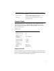
Specifications Sensor SecuGen FOR Image Capture Speed 600ms / frame Image Transfer Speed 500Byte / ms Pixel Resolution 356 x 292 USB Signaling Type Full Speed Type Theory of Operation The USB host initiates communication with the FDU01 using operation commands (Sensor LED On, Fingerprint Capture Start and Stop). Fingerprint data are then captured by the CMOS sensor at a total image size of 356 x 292 with 8-bit gray level. The image frame transfer speed is 500 bytes/ms.
Six Port USB Hub The Hub provides 4 internal USB ports to be used by the credit card reader, the fingerprint reader, the touchscreen, and the customer display. The hub also supplies two USB ports to the outside of the back of the 1229L for external use. The hub is only used by the USB version of the 1229L. The hub meets the following requirements: Specification Full compliance with USB specification 1.0, 1.1 and HID Class Definition Rev 1.0.
1-6 Elo Entuitive Touchmonitor User Guide
C H A P T E R INSTALLATION AND SETUP CHAPTER2 This chapter discusses how to install your LCD touchmonitor and how to install Elo TouchSystems driver software.
Product Overview Main Unit Rear View 2-8 Elo Entuitive Touchmonitor User Guide
Side View Base Bottom View 2-9
Kensington™ Lock The Kensington™ lock is a security device that prevents theft. To find out more about this security device, go to http://www.kensington.com.
Serial Interface Connection Your touchmonitor comes with one of the following touchscreen connector cables: Serial (RS-232) cable or USB cable. (For Windows 98, 2000, Me and XP systems only.) To set up the display, please refer to the following figures and procedures: Remove the Back Cover The cables are connected at the back of the monitor. back cover • To remove the cover, grasp the lip of the cover and pull towards you until it snaps off.
CAUTION NOTE: 2-12 Before connecting the cables to your touchmonitor and PC, be sure that the computer and touchmonitor are turned off. Before connecting the cables to the touchmonitor, route all the cables through the hole in the stand as shown in the picture above.
Serial Connection Option The following illustrations guide you step by step in connecting your touchmonitor using a serial cable connection. video cable • Connect one end of the video cable to the rear side of computer and the other to the LCD monitor. Tighten by turning the two thumb screws clockwise to ensure proper grounding.
power cable cable management clip • Connect one end of the brick power supply to the monitor and the other end to the connector of the power cable. • Connect the power cable to the power port in the monitor. • After connecting the power cable, secure the cable under the cable management clip.
speaker cable • Connect one end of the speaker cable to the speaker port in the computer and the other end to the port in the monitor • After connecting the speaker cable, secure it under the cable management clip.
touchscreen cable cable management clip • Connect one end of the serial touchscreen cable to the rear side of computer and the other to the LCD monitor.
MSR cable • Connect one end of the MSR cable to the computer and the other end to the monitor.
customer display cable Connect one end of the customer display cable to the computer and the other end to the monitor. Secure the cable under the cable management clip. • Press the power button on front panel to turn the monitor power on.
USB Interface Connection The following illustrations guide you step by step in connecting your touchmonitor using a USB cable connection. video cable • Connect one end of the video cable to the rear side of computer and the other to the LCD monitor. Tighten by turning the two thumb screws clockwise to ensure proper grounding.
power cable cable management clip • Connect one end of the brick power supply to the monitor and the other end to the connector of the power cable. • Connect the power cable to the power port in the monitor. • After connecting the power cable, secure it under the cable management clip.
speaker cable • Connect one end of the speaker cable to the speaker port in the computer and the other end to the port in the monitor.
self powered USB 1.1 Hub USB cable cable management clip • Connect one end of the USB cable to the rear side of the computer and the other to the LCD monitor. Secure the cable under the cable management clip. • The USB cable is for optional touch, MSR, CD and Finger Print Reader. Only one USB cable is needed because the device contains a self powered USB 1.1 Hub. Two self powered ports are available for running other USB devices. For touch only, no USB Hub is present.
Replace the Back Cover back cover lip cables • When you have attached all the cables to the monitor, gently bring all the cables toward the stand so they fit under the cover lip. • Snap the back cover in place over the connections.
Optimizing the LCD Display To ensure the LCD display works well with your computer, configure the display mode of your graphic card to make it less than or equal to 800 x 600 resolution, and make sure the timing of the display mode is compatible with the LCD display. Refer to Appendix A for more information about resolution. Compatible video modes for your touchmonitor are listed in Appendix C. Installing the Peripheral Device Drivers Finger Print Reader NOTE: This driver is for MS Windows 9x through XP.
Magnetic Stripe Reader No drivers are needed. Testing the Serial Version: 1 Insure the MSR serial is connected. (Make a note of the serial port, COM1, COM2, etc. it is connected to.) 2 Launch HyperTerminal 3 Go to file>new connection and type “MSR” then select OK. 4 In the Connect to Menu select Com port used in step one, then select OK.
Rear Facing Customer Display Serial Customer Display The serial customer displays do not need drivers. To get an image on the display: 1 Plug the DB-9 connector into serial port COM1 of computer. 2 Plug the RJ-45 cable into display. 3 In windows click on Start > Run 4 Enter cmd > OK 5 Type MODE COM1 96,N,8,1 > Enter 6 Type TYPE CON > COM1 > Enter 7 Type ELO > Enter The display will show ELO. USB Customer Display Plug in the USB cable attached to the Customer Display unit.
To test the drivers: 1 In windows click on Start > Run 2 Enter "cmd" > OK 3 Type "ECHO ELO>\.\LCLD9\" > Enter The display will show ELO. Installing the Touch Driver Software Elo TouchSystems provides driver software that allows your touchmonitor to work with your computer. Drivers are located on the enclosed CD-ROM for the following operating systems: • Windows XP • Windows 2000 • Windows Me • Windows 98 • Windows 95 • Windows NT 4.0 • CE 2.x, 3.0, 4x • Windows XP Embedded • Windows 3.
Installing the Serial Touch Driver Installing the Serial Touch Driver for Windows XP, Windows 2000, Me, 95/98 and NT 4.0 NOTE: For Windows 2000 and NT 4.0 you must have administrator access rights to install the driver. 1 Insert the Elo CD-ROM in your computer’s CD-ROM drive. 2 If the AutoStart feature for your CD-ROM drive is active, the system automatically detects the CD and starts the setup program. 3 Follow the directions on the screen to complete the driver setup for your version of Windows.
Installing the Serial Touch Driver for MS-DOS and Windows 3.1 You must have a DOS mouse driver (MOUSE.COM) installed for your mouse if you wish to continue using your mouse along with your touchmonitor in DOS. To install Windows 3.x and MS-DOS from Windows 95/98, follow the directions below: 1 Insert the Elo CD-ROM in your computer’s CD-ROM drive. 2 From DOS, type d:\EloDos_W31 to change to the correct directory on the CD-ROM (your CD-ROM drive may be mapped to a different drive letter).
Installing the USB Touch Driver Installing the USB Touch Driver for Windows XP, Windows 2000, Me and 98 1 Insert the Elo CD-ROM in your computer’s CD-ROM drive. If Windows XP, Windows 2000,Windows 98, or Windows Me starts the Add New Hardware Wizard: 2 Choose Next. Select “Search for the best driver for your device (Recommended)” and choose Next. 3 When a list of search locations is displayed, place a checkmark on “Specify a location” and use Browse to select the \EloUSB directory on the Elo CD-ROM.
C H A P T E R OPERATION CHAPTER3 About Touchmonitor Adjustments Your touchmonitor will unlikely require adjustment. Variations in video output and application may require adjustments to your touchmonitor to optimize the quality of the display. For best performance, your touchmonitor should be operating in native resolution, that is 800x600 at 60-75 Hz. Use the Display control panel in Windows to choose 800x600 resolution. Operating in other resolutions will degrade video performance.
Control Function 1 Power Switch Turns the display system power on or off. 2 Select Displays the OSD menus on the screen and used to select (“Up” and “Down” direction) the OSD control options on the screen. (1) Adjusts the decreasing value of the selected OSD control option. 3 4 5 3-32 Menu Elo Entuitive Touchmonitor User Guide (1) Adjusts the increasing value of the selected OSD control option. (2) Enables/disables the mute and volume option. Menu display and menu exit.
Controls and Adjustment OSD Lock/Unlock You are able to lock and unlock the OSD feature. The monitor is shipped in the unlocked position. To lock the OSD: 1 Press the Menu button and button simultaneously for 2 seconds. A window will appear displaying “OSD Unlock”. Continue to hold the buttons down for another 2 seconds and the window toggles to “OSD Lock”. Power Lock/Unlock You are able to lock/unlock the Power feature. The monitor is shipped in the unlocked position.
OSD Control Options Brightness • Background Luminance of the LCD panel is adjusted. Contrast • Adjusts the contrast or the values of color gain (RED, GREEN or BLUE). Saturation, Hue, Flesh Tones • Adjusts the color intensity and tint so faces appear natural. Phase • Adjusts the phase of the dot clock. Auto Adjust • Clock system auto adjustment (under 5 seconds). OSD Left/Right • The OSD screen is moved vertically right and left. OSD Up/Down • The OSD screen is moved vertically up and down.
Language • Languages used for OSD menu display: English, French, German, Spanish and Japanese. Recall Defaults • Recalls the factory OSD default settings. OSD Timeout • Adjusts the amount of time in which the OSD will disappear. Power-Save (No Input) • The LCD panel background is cut when there is no signal input (AC line power consumption of 5w or less). Power LED Display & Power Saving General Power Saving Mode When the power switch are switch on, this LED lights in green.
CAUTION 3-36 In order to protect the LCD, be sure to hold the base when adjusting the LCD, and take care not to touch the screen.
C H A P T E R TROUBLESHOOTING CHAPTER4 If you are experiencing trouble with your touchmonitor, refer to the following table. If the problem persists, please contact your local dealer or our service center. Elo Technical Support numbers are listed on the last page of this manual. Solutions to Common Problems Problem Suggestion(s) The monitor does not respond after you turn on the system. Check that the monitor’s Power Switch is on.
4-38 Elo Entuitive Touchmonitor User Guide
A P P E N D I X NATIVE RESOLUTION CHAPTER4 The native resolution of a monitor is the resolution level at which the LCD panel is designed to perform best. For the Elo LCD touchmonitor, the native resolution is 800 x 600 for the 12.1 inch size. In almost all cases, screen images look best when viewed at their native resolution. You can lower the resolution setting of a monitor but not increase it. Input Video 12.
As an example, a SVGA resolution LCD panel has 800 pixels horizontally by 600 pixels vertically. Input video is also represented by the same terms. XGA input video has a format of 1024 pixels horizontally by 768 pixels vertically. When the input pixels contained in the video input format match the native resolution of the panel, there is a one to one correspondence of mapping of input video pixels to LCD pixels.
A P P E N D I X TOUCHMONITOR SAFETY CHAPTER4 This manual contains information that is important for the proper setup and maintenance of your touchmonitor. Before setting up and powering on your new touchmonitor, read through this manual, especially Chapter 2 (Installation), and Chapter 3 (Operation). 1 To reduce the risk of electric shock, follow all safety notices and never open the touchmonitor case.
Care and Handling of Your Touchmonitor The following tips will help keep your Elo Entuitive touchmonitor functioning at the optimal level. • To avoid risk of electric shock, do not disassemble the brick supply or display unit cabinet. The unit is not user serviceable. Remember to unplug the display unit from the power outlet before cleaning. • Do not use alcohol (methyl, ethyl or isopropyl) or any strong dissolvent. Do not use thinner or benzene, abrasive cleaners or compressed air.
A P P E N D I X TECHNICAL SPECIFICATIONS CHAPTER4 Display Modes Your Elo Entuitive touchmonitor is compatible with the following standard video modes: Item Resolution Type H. Scan(KHz) V. Scan(Hz) Pol. 1 640X350 VGA 31.469 70.087 +/- 2 640X350 VESA85 37.861 85.080 +/- 3 720X400 VGA 31.469 70.087 -/+ 4 720X400 VESA85 37.927 85.039 -/+ 5 640X480 VGA 31.469 59.940 -/- 6 640X480 VESA72 37.861 72.809 -/- 7 640X480 VESA75 37.500 75.
Touchmonitor Specifications Model ET1229L LCD Display Display Size Pixel Pitch Display Mode 12.1” TFT Active Matrix Panel 246(H) x 184.5(V) mm 0.3075(H) x 0.3075(V) mm VGA 640 x 350 (70 / 85Hz) VGA 720 x 400 (70 / 85Hz) VGA 640 x 480 (60 / 72 / 75 / 85Hz) SVGA 800 x 600 (56 / 60 / 72 / 75Hz) Native Max.
AccuTouch Touchscreen Specifications Mechanical Construction Positional Accuracy Touchpoint Density Touch Activation Force Surface Durability Expected Life Performance Top: Polyester with outside hard-surface coating with clear or antiglare finish. Inside: Transparent conductive coating. Bottom: Glass substrate with uniform resistive coating. Top and bottom layers separated by Elo-patented separator dots. Standard deviation of error is less than 0.080 in. (2.03 mm). This equates to less than ±1%.
IntelliTouch Touchscreen Specifications Mechanical Positional Accuracy Touchpoint Density Touch Activation Force Surface Durability Expected Life Performance Sealing Standard deviation of error is less than 0.080 in. (2.03 mm). Equates to less than ±1%. More than 100,000 touchpoints/in2 (15,500 touchpoints/cm2). Typically less than 3 ounces (85 grams). Surface durability is that of glass, Mohs’ hardness rating of 7. No known wear-out mechanism, as there are no layers, coatings, or moving parts.
Infrared Touchscreen Specifications Mechanical Input Method Electrical Positional Accuracy Resolution Touch Activation Force Controller Optical Light Transmission Environmental Chemical Resistance Durability Surface Durability Input Method Finger or gloved hand activation Typical centroid accuracy: 2 mm with 1 mm STD error Touchpoint density is based on controller resolution of 4096 x 4096 No minimum touch activation force is required Board: Serial (RS232) or USB 1.
12.
C-49
C-50 Elo Entuitive Touchmonitor User Guide
REGULATORY INFORMATION CHAPTER4 I. Electrical Safety Information: A) Compliance is required with respect to the voltage, frequency, and current requirements indicated on the manufacturer’s label. Connection to a different power source than those specified herein will likely result in improper operation, damage to the equipment or pose a fire hazard if the limitations are not followed. B) There are no operator serviceable parts inside this equipment.
This Information Technology Equipment (ITE) is required to have a CE Mark on the manufacturer’s label which means that the equipment has been tested to the following Directives and Standards: This equipment has been tested to the requirements for the CE Mark as required by EMC Directive 89/336/EEC indicated in European Standard EN 55 022 Class B and the Low Voltage Directive 73/23/EEC as indicated in European Standard EN 60 950.
MPRII This Class B digital apparatus complies with Canadian ICES-003. Cet appareil numérique de la classe B est conforme à la norme NMB-003 du Canada.
54 Elo Entuitive Touchmonitor User Guide
WARRANTY CHAPTER4 Except as otherwise stated herein or in an order acknowledgment delivered to Buyer, Seller warrants to Buyer that the Product shall be free of defects in materials and workmanship. With the exception of the negotiated warranty periods; the warranty for the touchmonitor and components of the product is 2 years. Seller makes no warranty regarding the model life of components.
THESE REMEDIES SHALL BE THE BUYER’S EXCLUSIVE REMEDIES FOR BREACH OF WARRANTY. EXCEPT FOR THE EXPRESS WARRANTY SET FORTH ABOVE, SELLER GRANTS NO OTHER WARRANTIES, EXPRESS OR IMPLIED BY STATUTE OR OTHERWISE, REGARDING THE PRODUCTS, THEIR FITNESS FOR ANY PURPOSE, THEIR QUALITY, THEIR MERCHANTABILITY, THEIR NONINFRINGEMENT, OR OTHERWISE. NO EMPLOYEE OF SELLER OR ANY OTHER PARTY IS AUTHORIZED TO MAKE ANY WARRANTY FOR THE GOODS OTHER THAN THE WARRANTY SET FORTH HEREIN.
INDEX Numerics 12.
N Native Resolution, 39 O Optical, AccuTouch, 45 Optical, IntelliTouch, 46 Optical, IR, 47 Optimizing the LCD Display, 24 OSD Control Options, 34 OSD Left/Right, 34 OSD Lock/Unlock, 33 OSD Menu Functions, 33 OSD Position, 34 OSD Timeout, 35 OSD Up/Down, 34 P Phase, 34 Positional Accuracy, AccuTouch, 45 Positional Accuracy, IntelliTouch, 46 Positional Accuracy, IR, 47 Power LED Display & Power Saving, 35 Power Lock/Unlock, 33 Power-Save (No Input), 35 Product Description, 1 Product Overview, 8 R Rear Faci
USB (UNIVERSAL SERIAL BUS) KEYBOARD EMULATION SWIPE READER TECHNICAL REFERENCE MANUAL Manual Part Number 99875206 Rev 6 JUNE 2003 REGISTERED TO ISO 9001:2000 20725 South Annalee Avenue Carson, CA 90746 Phone: (310) 631-8602 FAX: (310) 631-3956 Technical Support: (651) 415-6800 www.magtek.
Copyright© 2001-2003 MagTek®, Inc. Printed in the United States of America Information in this document is subject to change without notice. No part of this document may be reproduced or transmitted in any form or by any means, electronic or mechanical, for any purpose, without the express written permission of MagTek, Inc. MagTek is a registered trademark of MagTek, Inc.
Limited Warranty MagTek, Inc. warrants that the Product described in this document is free of defects in materials and workmanship for a period of one year from the date of purchase where the date of purchase is defined as the date of shipment from MagTek.
FCC WARNING STATEMENT This equipment has been tested and found to comply with the limits for Class B digital device, pursuant to Part 15 of FCC Rules. These limits are designed to provide reasonable protection against harmful interference when the equipment is operated in a residential environment. This equipment generates, uses, and can radiate radio frequency energy and, if not installed and used in accordance with the instruction manual, may cause harmful interference to radio communications.
TABLE OF CONTENTS SECTION 1. FEATURES AND SPECIFICATIONS.....................................................................................1 FEATURES ...............................................................................................................................................1 HARDWARE CONFIGURATIONS ...........................................................................................................2 ACCESSORIES ......................................................................
OPERATION ...........................................................................................................................................25 SOURCE CODE .....................................................................................................................................26 FIGURES Figure 1-1. Figure 1-2. Figure 2-1. Figure 2-2.
vii
Figure 1-1.
SECTION 1. FEATURES AND SPECIFICATIONS The USB (Universal Serial Bus), HID Keyboard Emulation, Swipe Reader is a compact magnetic stripe card reader, which conforms to ISO standards. The Reader is compatible with the PC series of personal computers or any device with a USB interface. A card is read by sliding it, stripe down and facing the LED side, through the slot either forward or backward.
USB HID Keyboard Emulation Swipe Reader • Many programmable configuration options • Non-volatile flash EEPROM memory for configuration storage • Built-in 6 foot USB cable HARDWARE CONFIGURATIONS The hardware configurations are as follows: Part Number 21040107 21040109 Tracks TK 1,2,3 TK 1,2 Color Pearl White Pearl White ACCESSORIES The accessories are as follows: Part Number 21042806 99510026 Description USB MSR Demo Program with Source Code (Diskette) USB MSR Demo Program with Source Code (WEB) REFER
Section 1. Features and Specifications Table 1-2. Specifications Reference Standards Power Input Recording Method Message Format Card Speed MTBF Current Normal Mode Suspend Mode ISO 7810 and ISO 7811/CDL/ AAMVA* 5V From USB port Two-frequency coherent phase (F2F) ASCII 3 to 50 IPS Electronics: 125,000 hours. Head: 1,000,000 passes ELECTRICAL 30mA 300uA MECHANICAL (STANDARD PRODUCT) Weight Cable length Connector Temperature Operating Storage Humidity Operating Storage Altitude Operating Storage 4.5 oz.
USB HID Keyboard Emulation Swipe Reader 4
SECTION 2. INSTALLATION This section describes the cable connection, the Windows Plug and Play Setup, and the physical mounting of the unit. USB CONNECTION Connect the USB cable to a USB port on the host. The Reader, LED Indicator, and pin numbers for the 4-pin connector are shown in Figure 2-1. 1 4 LED Indicator Figure 2-1. Reader Cable and Connector Pin numbers and signal descriptions for the cable shown in the illustration are listed in Table 1-1. Table 2-1.
USB HID Keyboard Emulation Swipe Reader WINDOWS PLUG AND PLAY SETUP On hosts with the Windows operating system, the first time the device is plugged into a specific USB port, Windows will pop up a dialog box, which will guide you through the process of installing a device driver for the device. After this process is completed once, Windows will no longer request this process as long as the device is plugged into the same USB port.
Section 2. Installation Figure 2-2. Mounting Hole Dimensions For Surface 2. Ensure the Reader is positioned on a flat, accessible surface with at least 4 inches clearance on either end for room to swipe a card. Orient the Reader so the side with the LED is facing the direction of intended use. If fastening tape is to be used, clean the area that the Reader will be mounted on with isopropyl alcohol. Remove the adhesive protective cover on the fastening tape, and position the Reader and push down firmly.
USB HID Keyboard Emulation Swipe Reader 8
SECTION 3. OPERATION This section describes the LED Indicator and Card Read. LED INDICATOR The LED indicator will be either off, red, or green. When the device is not powered, the LED will be off. When the device is first plugged in, the LED will be red. As soon as the device is plugged in, the host will try to enumerate the device. Once the device is enumerated the LED will turn green indicating that the device is ready for use.
USB HID Keyboard Emulation Swipe Reader 10
SECTION 4. USB COMMUNICATIONS This device conforms to the USB specification revision 1.1. This device also conforms with the Human Interface Device (HID) class specification version 1.1. The device communicates to the host as a HID keyboard device. The latest versions of the Windows operating systems, Windows 98, Me, and 2000, all come with a standard Windows USB HID keyboard driver. This is a full speed USB device. This device is powered from the USB bus.
USB HID Keyboard Emulation Swipe Reader Tk1 SS Tk2 SS = = Tk3 SS = ES CR = = % (7-bit start sentinel) ; (ISO/ABA 5-bit start sentinel) @ (7-bit start sentinel) + (ISO/ABA start sentinel) ! (CA drivers licence start sentinel) # (AAMVA start sentinel) & (7-bit start sentinel) ? (end sentinel) (carriage return) (0D hex) All data will be sent in upper case regardless of the state of the caps lock key on the keyboard. If no data is detected on a track then nothing will be transmitted for that track.
Section 4. USB Communications the device so that the application developer is not burdened with these low level details. Details on how to communicate with the device to change programmable configuration properties follows in the next few sections. These details are included as a reference only. Most users will not need to know these details because the device will be configured at the factory or by a program supplied by MagTek.
USB HID Keyboard Emulation Swipe Reader REPORT DESCRIPTOR The HID report descriptor is structured as follows: Item Usage Page (Generic Desktop) Usage (Keyboard) Collection (Application) Usage Page (Key Codes) Usage Minimum (224) Usage Maximum (231) Logical Minimum (0) Logical Maximum (1) Report Size (1) Report Count (8) Input (Data, Variable, Absolute) Report Count (1) Report Size (8) Input (Constant) Report Count (5) Report Size (1) Usage Page (LEDs) Usage Minimum (1) Usage Maximum (5) Output (Data, Vari
Section 4. USB Communications COMMANDS Command requests and responses are sent to and received from the device using feature reports. Command requests are sent to the device using the HID class specific request Set_Report. The response to a command is retrieved from the device using the HID class specific request Get_Report. These requests are sent over the default control pipe. When a command request is sent, the device will Nak the Status stage of the Set_Report request until the command is completed.
USB HID Keyboard Emulation Swipe Reader RESULT CODE This one byte field contains the value of the result code. There are two types of result codes: generic result codes and command specific result codes. Generic result codes always have the most significant bit set to zero. Generic result codes have the same meaning for all commands and can be used by any command. Command specific result codes always have the most significant bit set to one.
Section 4. USB Communications Property ID is a one byte field that contains a value that identifies the property.
USB HID Keyboard Emulation Swipe Reader SERIAL_NUM PROPERTY Property ID: 1 Property Type: String Length: 0 – 15 bytes Get Property: Yes Set Property: Yes Default Value: The default value is no string with a length of zero. Description: The value is an ASCII string that represents the device’s serial number. This string can be 0 – 15 bytes long. This property is stored in non-volatile EEPROM memory so it will not change when the unit is power cycled.
Section 4. USB Communications memory so it will not change when the unit is power cycled. The value of this property, if any, will be sent to the host when the host requests the device’s USB endpoint descriptor. When this property is changed, the unit must be power cycled to have these changes take effect for the USB descriptor. If a value other than the default value is desired, it can be set by the factory upon request.
USB HID Keyboard Emulation Swipe Reader TRACK_DATA_SEND_FLAGS PROPERTY Property ID: Property Type: Length: Get Property: Set Property: Default Value: Description: 0 4 Byte 1 byte Yes Yes 63 (hex) This property is defined as follows: SS ES LRC 0 LC Er Er SS 0 – Don’t send Start Sentinel for each track 1 – Send Start Sentinel for each track ES 0 – Don’t send End Sentinel for each track 1 – Send End Sentinel for each track LRC 0 – Don’t send LRC for each track 1 – Send LRC for each track Note tha
Section 4. USB Communications Set Property: Default Value: Description: mod Yes 0D (hex) (carriage return) This property is defined as follows: c c c c c c mod 0 – Send c after card data 1 – Send c after each track c 1-127 – 7 bit ASCII char code 0 – send nothing c This property is stored in non-volatile EEPROM memory so it will not change when the unit is power cycled. When this property is changed, the unit must be power cycled to have these changes take effect.
USB HID Keyboard Emulation Swipe Reader This property is stored in non-volatile EEPROM memory so it will not change when the unit is power cycled. When this property is changed, the unit must be power cycled to have these changes take effect. If a value other than the default value is desired, it can be set by the factory upon request.
Section 4. USB Communications Description: This character is sent as the track 3 start sentinel for cards that have track 3 encoded in 7 bits per character format. If the value is 0 no character is sent. If the value is in the range 1 – 127 then the equivalent ASCII character will be sent. This property is stored in non-volatile EEPROM memory so it will not change when the unit is power cycled. When this property is changed, the unit must be power cycled to have these changes take effect.
USB HID Keyboard Emulation Swipe Reader PRE_TK_CHAR PROPERTY Property ID: 13 (0D hex) Property Type: Byte Length: 1 byte Get Property: Yes Set Property: Yes Default Value: 0 Description: This character is sent prior to the data for each track. If the value is 0 no character is sent. If the value is in the range 1 – 127 then the equivalent ASCII character will be sent. This property is stored in non-volatile EEPROM memory so it will not change when the unit is power cycled.
SECTION 5. DEMO PROGRAM The purpose of this demo program is not to demonstrate card reading with this HID keyboard emulation device. Use a text editor application such as Windows Notepad to demonstrate card reading for this HID keyboard emulation device. Any application that allows user input from a keyboard should be sufficient to demonstrate card reading for this device.
USB HID Keyboard Emulation Swipe Reader • • • length for you. For example, to send the GET_PROPERTY command for property SOFTWARE_ID enter 00 00. Press Enter or click on Send message to send the command and receive the result. The command request and the command result will be displayed in the Communications Dialog edit box. The Clear Dialog button clears the Communication Dialog edit box. SOURCE CODE Source code is included with the demo program. It can be used as a guide for application development.
PORT POWERED SWIPE READER TECHNICAL REFERENCE MANUAL Manual Part Number 99875094 Rev 10 JULY 2001 20725 South Annalee Avenue Carson, CA 90746 Phone: (310) 631-8602 FAX: (310) 631-3956 Technical Support: (888) 624-8350 www.magtek.
Copyright 1997-2001 MAG-TEK, Inc. Printed in the United States of America Information in this document is subject to change without notice. No part of this document may be reproduced or transmitted in any form or by any means, electronic or mechanical, for any purpose, without the express written permission of Mag-Tek, Inc. Mag-Tek is a registered trademark of Mag-Tek, Inc. Procomm is a registered trademark of Datastorm Technologies, Inc.
Limited Warranty Mag-Tek, Inc. (hereinafter “Mag-Tek”) warrants this Mag-Tek product IN ITS ENTIRETY, to be in good working order for a period of one year from the date of purchase from Mag-Tek. Should this product fail to be in good working order at any time during this warranty period, Mag-Tek will, at its option, repair or replace this product at no additional charge except as set forth below.
FCC WARNING STATEMENT This equipment has been tested and found to comply with the limits for Class B digital device, pursuant to Part 15 of FCC Rules. These limits are designed to provide reasonable protection against harmful interference when the equipment is operated in a residential environment. This equipment generates, uses, and can radiate radio frequency energy and, if not installed and used in accordance with the instruction manual, may cause harmful interference to radio communications.
TABLE OF CONTENTS SECTION 1.
Figure 1-1.
SECTION 1. FEATURES AND SPECIFICATIONS The Port Powered Swipe Reader is a compact magnetic stripe card reader which conforms to ISO/ANSI standards. The Reader is compatible with the PC series of personal computers or any device with a serial RS-232 interface. A card is read by sliding it, stripe down and facing the LED side, through the slot either forward or backward. A green LED (Light Emitting Diode) indicator on the Reader panel provides the operator with continuous status of the Reader operations.
Port Powered Swipe Reader CONFIGURATION The Reader, LED Indicator, pin numbers for the 9-pin connector, and the Adapter are shown in Figure 1-2. Figure 1-2. Reader Cable and Optional Adapter Pin numbers and signal descriptions for the 9-pin (DE9) cable and 25-pin (DB25) adapter shown in the illustration are listed in Table 1-1. Also listed is the pin list OEM version, P/N 21040077. Table 1-1.
Section 1. Features and Specifications SPECIFICATIONS Table 1-2 lists the specifications for the Port Powered Swipe Reader. Figure 1-3 shows the dimensions for the standard product. Other sizes are available by special order. Table 1-2.
Port Powered Swipe Reader Figure 1-3.
SECTION 2. INSTALLATION The hardware installation consists of plugging the cable into the PC and optional adapter, if required, Com Port setup, and testing the Reader. REQUIREMENTS • • • • Port Powered Swipe Reader Optional 9- to 25-pin Adapter, P/N 78200018 PC with Com Port Procomm, Hyper Terminal, Mag-Tek Windows Drivers, or other RS-232 communications program MOUNTING 1.
Port Powered Swipe Reader Figure 2-1. Mounting Hole Dimensions For Surface 3. Mount the Reader. INSTALLATION AND TEST To install the Swipe Reader, perform the following steps: 1. Connect the Swipe Reader cable connector into a 9-pin serial Com Port on the PC. If a 25-pin Adapter is required, plug the 9-pin connector on the Reader into the Adapter, and the adapter into the PC. 2.
Section 2. Installation 6. Select 8 data bits, no parity, 1 stop bit. 7. With the LED on, swipe a card. The data on the screen will show Track 1 beginning with “%” and ending with “?”. Track 2 begins with “;” and ends with “?”. Track 3 begins with “+” (normal) or "!" (CDL) and ends with “?”.
Port Powered Swipe Reader 8
SECTION 3. OPERATION Included in this section are Indicator, Card Read, Reader to Host Message Format, and a timing diagram of sign-on ID. LED INDICATOR A green LED indicator on the panel gives the operator the status of the Reader. If the cabling is correct and the correct Com Port is selected, the indicator will be on. If the indictor does not come on, check the cabling and the Com Port. The LED is turned off during a card swipe and while the unit is transmitting.
Port Powered Swipe Reader TIMING FOR ID SIGN ON Timing for the ID Sign-on and transmission bursts (5 ms with 10 ms between bursts) are shown in Figure 3-1. DTR 150 ms Sign-on ID Transmission Burst 5 ms 10 ms Figure 3-1. Timing For ID Sign-on and Transmission Bursts.
Section 3. Operation Table 3-2 lists the available part number, firmware, and configuration. Table 3-2.
Port Powered Swipe Reader 12
MAGTEK DEVICE DRIVERS FOR WINDOWS PROGRAMMING REFERENCE MANUAL Manual Part Number: 99875125 Rev 6 NOVEMBER 2001 20725 South Annalee Avenue Carson, CA 90746 Phone: (310) 631-8602 FAX: (310) 631-3956 Technical Support: (888) 624-8350 www.MagTek.
Copyright 1996-2001 MAG-TEK, Inc. Printed in the United States of America Information in this document is subject to change without notice. No part of this document may be reproduced or transmitted in any form or by any means, electronic or mechanical, for any purpose, without the express written permission of Mag-Tek, Inc. MagTek is a registered trademark of Mag-Tek, Inc.
Limited Warranty Mag-Tek, Inc. (hereinafter “Mag-Tek”) warrants this Mag-Tek product IN ITS ENTIRETY, to be in good working order for a period of 90 days from the date of purchase from Mag-Tek. Should this product fail to be in good working order at any time during this warranty period, Mag-Tek will, at its option, repair or replace this product at no additional charge except as set forth below.
TABLE OF CONTENTS SECTION 1. OVERVIEW ................................................................................................................1 PROBLEMS WITH CONTROLLING DEVICES ...........................................................................1 BENEFITS OF A CONTROL LANGUAGE AND DRIVER ...........................................................2 LANGUAGE OVERVIEW .............................................................................................................3 Properties.......
enc_key..................................................................................................................................13 enc_key_sn............................................................................................................................13 enc_mode ..............................................................................................................................13 entry_echo ......................................................................................
DESCRIPTION...........................................................................................................................30 LANGUAGE FORMAT ...............................................................................................................31 Format Name .........................................................................................................................31 Format Template..............................................................................................
MT-95 HICO ENCODER............................................................................................................88 INDEX.............................................................................................................................................89 FIGURES Figure 1-1. MagTek Devices and Device Drivers for Windows.....................................................viii Figure A-1. Properties Settings, Windows 95 ...................................................................
MTD MagTek Device Drivers for Windows Figure 1-1.
SECTION 1. OVERVIEW The MagTek Device (MTD) Drivers for Windows is a collection of individual drivers that support a number of MagTek products. These drivers provide a uniform application interface for controlling a wide range of MagTek devices. The drivers, combined with a device control language, solve many of the difficulties application developers face when attempting to control hardware devices.
MagTek Device Drivers for Windows • MagTek devices are attached to the host in different ways. MagTek devices may be attached to a serial port, parallel port, to another device or even to the keyboard port. All these ports differ greatly in nature and would all have to be accessed by the application. Additionally, meaningful communication with a device attached to the keyboard port would be tricky at best.
Section 1. Overview usually remain unchanged, even though the new device may be very different from the old one. The features of a driver that implement a device control language completely shield an application developer from the complexities of device-specific functionality. LANGUAGE OVERVIEW The device control language is text based and designed to utilize the read and write file I/O facilities of the underlying operating system.
MagTek Device Drivers for Windows COMMANDS Like properties, commands are identified by a string name and have string arguments. All commands are terminated by line feed or a carriage return. To invoke a command, an application simply writes it to the driver in the same manner as writing to a file or serial port. If the command has a response defined for it, the application reads it from the driver using the same I/O handle as in the write.
Section 1. Overview TYPICAL OPERATION This section describes a typical pattern that an application developer may use to operate a device. Although it is the most typical pattern, it is by no means the only viable one. Refer to Section 5, Example Applications, to see how to use the drivers in various applications. Open a device Access to the device is obtained by opening the comxx: port that the device was installed as.
MagTek Device Drivers for Windows instruct the device to return the card data when swiped. All the facilities of the driver are utilized during this stage of operation. Close the device When the application is finished with the device, it simply closes the port using the handle obtained when it opened it. The driver shuts down the device if required. Note In some cases with Windows 95, the Driver may not be closed properly.
Section 1. Overview Settings tab. This gives both the Friendly Name and the port name (COM<5-15>). It also identifies the physical port that will be used to communicate with the device. Open the device using either of the previous names. Use whatever facility is provided by your development environment for opening files. For Visual Basic, do the following: 'set error handling On Error Resume Next ‘open the port for binary access Open “\\.\micr+” For Binary Access Read Write As #1 If Err.
MagTek Device Drivers for Windows ‘set up error handling On Error Resume Next ‘submit echo command Put #1, , "/echo Hello" + Chr$(10) ‘declare an input buffer a$ = String(2000, Chr$(0)) ‘read echo response from device Get #1, , a$ If Err.Number <> 0 Then <> End If Note File I/O interaction with the device is synchronous; the read operation will block until a response is received from the device or is returned by the driver (as in a property request).
Section 1. Overview 1. It can prompt the user to repeat the action and re-submit the command. This is typical if the status does not indicate a failure, per se, but that the device may not be ready yet or first needs some other interaction by the user. 2. It can reset the device and prompt the user to repeat the action. Typically, this action is necessary if the device’s state or configuration has been corrupted, but is otherwise functioning correctly. 3.
MagTek Device Drivers for Windows Installation And Setup) and select Properties. Click on the Version tab. Note the File Version, Part Number, and Description. INSTALLATION The drivers are installed by means of the Windows “Add New Hardware” facility in Windows 95/98/ME and the "INF" installation feature in Windows NT/2000/XP. Refer to "Appendix A. Installation And Setup" for a full description of the installation procedure.
SECTION 2. PROPERTIES This section lists the properties that are used in the MagTek Drivers. Properties can be interrogated by issuing a get command and modified with a set command. Refer to Section 3. Commands for complete description and examples of all commands. The c_xxx properties are set by the driver and reflect the device’s capabilities. However, the c_xxx properties do not indicate the configuration of the device.
MagTek Device Drivers for Windows Property c_write c_wr_secure capitalize card_stat chk_account chk_amount chk_bankid chk_data chk_format chk_mod10 chk_number chk_routing chk_status chk_transit cmd_pending Access Description R 1 if the device can encode a magnetic card in either LoCo or HiCo; 2 if the device can encode a magnetic card in only the setting indicated in wr_coer R 0 if the device does not support secure mode; 1 if the device can switch between secure and non-secure mode (see wr_secure); 2
Section 2. Properties Property Access Description enc_key R/W Encryption key to use for the next encryption process (IntelliPIN): M for Master key S for Session key 0-3 for lower working keys A-J for upper working keys enc_key_sn R/W Serial number of encryption key. Used to specify key serial number for activating/deactivating PIN encryption in MSK mode and to return the key serial number in DUKPT mode. The key serial number is specified in clear text (IntelliPIN).
MagTek Device Drivers for Windows Property Access Description offline_enc R/W Set to 1 to enable encode capability in standalone mode with keyboard; 0 prevents standalone encoding (MT-95). oper_tout R/W Operational timeout in seconds (15-255). (IntelliPIN) pin_blk_fmt R/W PIN block format (IntelliPIN): ansi (ANSI 9.8) or ibm (IBM 3624) pinfilldig R/W PIN fill digit (0..9, A..F) when pin_blk_fmt is ibm (IntelliPIN) port_name R Indicates the virtual port number (e.g.
SECTION 3. COMMANDS This section describes all of the commands that can be used with the MagTek Windows Device Drivers. Some commands require parameters to indicate to the driver exactly what function is to be performed. While there are a few device-specific commands, most commands can be used with any device. DATA FORMAT All commands sent to the driver and all responses received are strings of printable ASCII characters delimited by . The driver will also accept as a delimiter.
MagTek Device Drivers for Windows Examples: 000000000011111111112222222222 012345678901234567890123456789 /read -00082 /get trk_enable 110 NOTATION CONVENTIONS The following conventions are used in the tables that follow. Fixed Size (Bold) Italic [] (a|b) Used to represent literals (symbols, exactly as sent or received from driver) Used to represent placeholders (variable fields) Expression parts in brackets are optional. The brackets are never a part of the syntax ASCII control character.
Section 3. Commands display Function Syntax Show a single message or two alternating messages on the device’s display. /display [x] The optional argument x indicates the message to be displayed. Errors none Remarks If the optional argument x is provided, this command displays it as a single message. If x is @, the driver sends a command to the device to display the idle message 00 (“Welcome”). If x is omitted, the command uses the values of the msg1 and msg2 properties for the message texts.
MagTek Device Drivers for Windows event Function Syntax Errors Remarks Response to an unsolicited event notification. none none This response can occur when an unsolicited event, such as card inserted, occurs.
Section 3. Commands load_key Function Syntax Errors Load an encryption key into the device. /load_key n key n can be one of the following values: M – master key (key is in clear text) S – session key (key is encrypted under Master Key) 0 ... 3 – lower working keys (key is encrypted under Session Key) A ... J – upper working keys (key is encrypted under Session Key) key is the 16- or 32-character value of the key to be loaded.
MagTek Device Drivers for Windows rawrecv Function Syntax Errors Receive data from the device. /rawrecv /rawrecv 45 If a command is already pending. /rawrecv 82 If the command was canceled by the user (e.g., with CLEAR key) Remarks This command overrides the default processing of the next message that comes from the device and returns it to the application as a rawrecv response.
Section 3. Commands rawsend Function Syntax Send arbitrary data to the device. /rawsend x x is an arbitrary string which is transmitted directly to the device. The string x is passed as-is to the device, except for ‘\’ which is used as an ‘escape’ character: • \r is converted to • \n is converted to • \\ is converted to \ • \xhh is converted to a character with ASCII value hh (always two hex digits), e.g., \x20 is converted to a space.
MagTek Device Drivers for Windows read Function Syntax Read data from the device. /read [[x] y] The optional argument x specifies the data source; if x is missing, a card will be read. Refer to the Read Argument table below for a description data sources. The optional argument y is used to specify a message to be displayed on the LCD screen, if supported, before carrying out the command. If y is omitted and the device supports a display, the text in the msg1 property is shown.
Section 3. Commands Read Arguments The optional argument x used in the read command specifies the type of data to read and y specifies the text to be displayed. The following table describes the recognized x arguments for the read command: Read Argument any card card_w_pin check Description Read any type of data. This option is equivalent to read without any arguments. Read magnetic stripe card. Display message (msg 1) if defined.
MagTek Device Drivers for Windows Read Argument chk_or_card key_press key_string 24 Description Read magnetic stripe card or check data. When a card or check is swiped through the device, the driver sends the respective response. Display a message (msg4) on the LCD screen, if available, and wait for a key on the keypad to be pressed. The device will wait for entry_tout seconds for the key press (by default 0 for no timeout).
Section 3. Commands Read Argument pin Description Collect PIN from cardholder and read PIN data from the device. The following properties may be set before issuing this command: • account_no – cardholder account number, including check digit, if required • amount – transaction amount in cents, without punctuation, if required • enc_key – (MSK mode only) encryption key to use: M for master, S for session, 0-3 for lower working keys, A-J for upper working keys.
MagTek Device Drivers for Windows reset Function Syntax Errors Remarks Reset the device. /reset none Clear any pending operations and reset the device to initial state (for mechanized card devices this command will also eject the card). This does not affect any of the properties. Example To return a device to its initial state: Command Response /reset none set Function Syntax Set a property. /set prop val prop is one of the valid properties (R/W) shown in Section 2.
Section 3. Commands write Function Syntax Errors Data encode command. /write data /write 94 Encode is not supported on this device. /write 34 The data field was in the incorrect format. /write 82 The write command was canceled. /write 45 Device in wrong mode (e.g., if /read already issued) /write 60 Error during write operation (e.g.
MagTek Device Drivers for Windows 28
SECTION 4. MAGNETIC CARD DATA PARSING This section describes the flexible data parsing language to be used by the MagTek device drivers to parse specific fields from magnetic card data and expose those fields as properties which may be retrieved by an application using the /get command. The data parsing language is flexible in that it can define both standard and custom formats to be parsed by the driver.
MagTek Device Drivers for Windows • • • Property names specified in format rules are 11 characters or less, consisting of alphabetic characters, digits, and ‘_’. The property name begins with an alphabetic character. Properties used in format strings do not conflict with properties defined by the driver. If there is a duplicate property (e.g., dev_version) specified in the format strings, the driver will return the value of the parsed property rather than the device version string.
Section 4. Magnetic Card Data Parsing If the driver is successful in applying one of the rules, the name of the applied format is available in the property applied_fmt. LANGUAGE FORMAT Format Name (fmtx_name) The format name specifies an identifier by which to identify the format template and/or rules being applied. The maximum length of this property is 11 characters. The names can be repeated on subsequent templates.
MagTek Device Drivers for Windows A format rule describes how the data is to be parsed. Characters that must be matched as literals are placed as is in the string or preceded with a ‘\’ if the character is one of the following: ‘[’, ‘]’, ‘(’, ‘)’, ‘*’, ‘_’, ‘<’, ‘>’, ‘:’, ‘.’, or ‘\’. Fields that are either to be parsed or ignored are contained within <>. The format rules string cannot exceed 1027 characters.
Section 4. Magnetic Card Data Parsing Field Type Literal Example ^ Non-ASCII literal \r, \n, \\, \xhh Optional choice (x|y|…) Optional field [x] Optional track {xy} Description A literal is placed in the string as is and is used to determine if a particular format should be applied and to mark the end of a variable-length field. Specify an escape character or non-ASCII character.
MagTek Device Drivers for Windows The property name can also contain a modifier at the end preceded by a ‘:’ which specifies the type of data to store in that property. For example specifies that customer name should contain alphabetic characters, spaces, and punctuation. The modifier may also be used with ignore-fields (i.e., <*>). If no modifier is provided, any type of characters is assumed.
Section 4. Magnetic Card Data Parsing DEFAULT FORMATS The MTD drivers will be assigned parameters with default formats for parsing magnetic stripe data. The formats will be placed in the INF file for the driver and written to the registry when the driver is installed. Some examples are shown below; more are included with the drivers. In these examples, spaces are inserted between fields for readability; they should not be included in the actual rules.
MagTek Device Drivers for Windows fmt5_name "AAMVA" fmt5_template"%<*>?;<*>?{(+|%|#|!)<*>?}" fmt5_rules "{%^$$^^<*>? ;<*[6]>=<*>? {(+|!|#|%)<*[2]><*[16]> <*>?}}, {%^$^^<*>? ;<*[6]>=<*>? {(+|!|#|%)<*[2]><*[16]> <*>?}}" In the examples for CADL (Califo
Section 4. Magnetic Card Data Parsing The application issues /get applied_fmt. The driver responds with /get applied_fmt BankCard. The application issues /get FirstName to the driver. The driver responds with /get FirstName JOHN. The application issues /get LastName to the driver. The driver responds with /get LastName SMITH. The application issues /get PAN to the driver. The driver responds with /get PAN 1234567890074589. The application issues /get ExpDate to the driver.
MagTek Device Drivers for Windows 38
SECTION 5. EXAMPLE APPLICATIONS While each application in this section is oriented toward a specific programming language, different devices are addressed in each example. It may be useful for the reader to look at all examples to understand how the MagTek Windows Drivers can operate with various MagTek devices. PROGRAMMING HINTS When opening a Keyboard Wedge device, the application must wait for any key press to complete, e.g., ALT-0. The application should wait until all keys have been released.
MagTek Device Drivers for Windows ' The form needs to contain: ' 1) an "MSComm" object named MSComm1 ' ' 2) a button named btnStart, should be set to Enabled and Visible with the caption "Start" ' ' 3) a button named btnRead, should be set to Disabled and Visible with caption "Read" ' ' 4) a button named btnExit, should be set to Enabled and Visible with caption "Exit" ' ' ' 5) a text box named txtInfo, should be set to Visible, Enabled and MultiLine containing initial text of "Click the Start butto
Section 5. Example Applications MSComm1.Output = "/read card" & Chr$(10) ' ' ' ' If the device has check reading capability, then the following command would be used to read only the check data MSComm1.Output = "/read check" & Chr$(10) ' ' ' ' If the device can read only one media type (e.g. a card reader) then the read command "/read" command can be is issued by itself. MSComm1.
MagTek Device Drivers for Windows ' will hold the numeric port number Dim PortNumber As Integer ' prevent the Start button from being pressed again btnStart.Enabled = False txtInfo.Text = "Please wait. txtInfo.Refresh Opening the port as File IO" ' declare space for an input buffer buf$ = String(2000, Chr$(0)) ' If the virtual serial port number is unknown, it can be ' obtained by opening the driver in "File" mode with ' the "Friendly Name" and asking for the virtual COM port number.
Section 5. Example Applications If Err.Number <> 0 Then ' Process error using Err.Description ' contains error description for the demo, ' we'll just display it txtInfo.Text = Err.
MagTek Device Drivers for Windows ' Set the com port number retrieved from the response MSComm1.CommPort = PortNumber ' Open the com port and establish communications with the device MSComm1.PortOpen = True ' enable the read button btnRead.Enabled = True txtInfo.Text = "Click on the Read button to read a” _ & “card or Exit to quit." Else ' If we got here, then the device did not open correctly ' as a file IO so some kind of error handling is needed txtInfo.
Section 5. Example Applications C++ EXAMPLE The following is an example of C++: /* /* /* /* /* /* /* -------------------------------------------------------------------------- */ TST: Test Application */ */ MTDTEST.C - Test module for Mag-Tek device drivers */ -------------------------------------------------------------------------- */ Version 1.00 $Revision:: $ */ -------------------------------------------------------------------------- */ #include #include #include #include
MagTek Device Drivers for Windows /** clear overlapped structure */ memset ( &ov_r, 0, sizeof (ov_r) ); memset ( &ov_w, 0, sizeof (ov_w) ); if (argc < 2) drv_h = OPEN_DEVICE ("COM5"); /* Must Specify proper COM# as default */ else drv_h = OPEN_DEVICE (argv[1]); if (drv_h == INVALID_HANDLE_VALUE) { ws = GetLastError(); printf("Can NOT open device : %s. Error : 0x%lx", "", ws); return ( stage); } { DCB dcb; GetCommState(drv_h, &dcb); dcb.BaudRate = CBR_9600; dcb.Parity = NOPARITY; dcb.ByteSize = 8; dcb.
Section 5. Example Applications NULL, // address of thread security attributes 0L, // initial thread stack size, in bytes (LPTHREAD_START_ROUTINE)input_thread,// addr of thread function NULL, // argument for new thread 0L, // creation flags 0-run immediately &retdw // address of returned thread identifier ), "Can't Create input thread" ); in_threadh = ret_h; Sleep(100); printf("\nTest Console started. (press <^Z> to terminate).
MagTek Device Drivers for Windows } #else gets(str); strcat(str, "\n"); ch = str[0]; #endif switch (ch) { case 0x1a: // - emergency exit printf("\n---Exit---\n");//@@ quit = TRUE; break; default: if (ch < 0x100) { BOOL rs; DWORD ret_len; #ifdef SINGLE_CHARS rs = WriteFile(drv_h, &ch, 1, &ret_len, &ov_w); #else rs = WriteFile(drv_h, str, strlen(str), &ret_len, &ov_w); #endif if (!rs) { ws = GetLastError (); if ( ws != ERROR_IO_PENDING) printf("DeviceIOControl (Write) Error : %i (0x%x)\n", ws, ws );
Section 5. Example Applications DWORD char char* read_len=0; wbuff[1]; p; while (!quit) { rs = ReadFile(drv_h, wbuff, sizeof(wbuff), &read_len, &ov_r); if ( !rs) { rs = GetLastError (); if ( rs != ERROR_IO_PENDING) { printf("DeviceIOControl (Read) Error : %i (0x%x)\n", rs, rs ); break; } } rs = WaitForSingleObject ( ov_r.
MagTek Device Drivers for Windows POWER BUILDER EXAMPLE The following example illustrates how to set up PowerBuilder (from Sybase) to read magnetic data from the IntelliPIN device. Since PowerBuilder does not interface to a serial port very easily, a third-party OCX is required. The first part of this application note shows how to load an ActiveX component. The main program script shows how to interface with the OCX, the MTD Windows Driver, and the MagTek device (in this case the IntelliPIN).
Section 5. Example Applications 8. Close the PowerScript Painter window and answer “Yes” to “Save changes…”. 9. Close the Window Painter window and answer “Yes” to “Save changes…”. At the “Save Window” dialog box, enter “ole_io” then click “OK”. 10. Open the PowerScript window for the main application and integrate the following commands into the application. (This demo application prompts the user to read a card. The program will continue to loop until the “Cancel” button is pushed.
MagTek Device Drivers for Windows 52
APPENDIX A. INSTALLATION AND SETUP The distribution disks contain the MTD Driver files for many of the MagTek products. In addition to the drivers, there are number of files that are required to support the installation and operation of these drivers. The disk contents are listed in the tables below. Some of the Drivers support multiple configurations of the associated product. For example, the IntelliPIN Driver (IPIN.VXD) provides an interface vehicle for three different interface configurations.
MagTek Device Drivers for Windows INSTALLING DEVICE DRIVERS (W95/98/ME) File or Directory Name Device Friendly Name DESCRIPTION OEMSETUP.INF Installation descriptor file README.TXT Describes the disk file contents and provides installation procedures \W95_DRV Directory The following Windows 95/98/ME device drivers are located in this directory: DMAPLD.VXD DriverMagic Advanced Part Library DMVXD.VXD DriverMagic engine DMVXDD.VXD DriverMagic Windows 9x/ME Driver Part Kit GENERIC.
Appendix A. Installation and Setup General Notes: 1. 2. 3. 4. The computer and device should be powered off when connecting any devices. Although you do not have to have the device connected to install the driver, it is highly recommended. This allows the device and driver to be tested when the driver is installed. Note which hardware port each device is using on the computer as this information will be used later in the driver installation process.
MagTek Device Drivers for Windows 5. 6. 7. 8. 9. Select MagTek from the list of Hardware Types, then click the Next button. Select the device to be installed from the displayed list box and click the Next button. Click the Finish button. The computer will take a moment to install the driver. Please be patient. If the installation file cannot be found, click Browse and point to where the installation file (oemsetup.inf) is located; click the OK button on the dialog box.
Appendix A. Installation and Setup 1. 2. 3. 4. 5. Either accept the default selection for the virtual Port Name or select the desired port (COM5-COM15) to be associated with the device from the Port Name combo box and modify the device’s friendly name if the default is not acceptable. Select the port to which the device is connected (see General Notes in Installing Device Drivers (W95/98/ME) above) from the Connect to combo box.
MagTek Device Drivers for Windows Figure A-1. Properties Settings, Windows 95/98/ME Figure A-2.
Appendix A. Installation and Setup Removing the Drivers (W95/98/ME) Caution The following assumes familiarity with the Registry Editor. Improper use of the Registry Editor can cause Windows to cease to function. Please follow the instructions carefully. Complete removal of the drivers requires two steps: (1) remove the drivers from the system using the Device Manager and (2) remove the driver files manually after all devices have been removed by the Device Manager.
MagTek Device Drivers for Windows MAGCDFLT.DLL MAGCxxx.HLP (locale specific) MAGCxxx.DLL (locale specific) 7. Find and remove the copy of the Mag-TekOEMSETUP.INF file made by Windows. In release 1 of Windows 95, it is located in C:\Windows\inf\. With the OSR2 release of Windows 95 (Win95B) and Windows 98/ME, the files will be located in C:\Windows\inf\other\. 8. Run the Registry Editor by clicking on Start button then select Run. Type REGEDIT into the text box and press the Enter key. 9.
Appendix A. Installation and Setup INSTALLING DEVICE DRIVERS (WNT) File or Directory Name Friendly Name DESCRIPTION OEMSETUP.INF Installation descriptor file README.TXT Describes the disk file contents and provides installation procedures \WNT_DRV Directory The following Windows NT device drivers are located in this directory: DMAPLD.DLL DriverMagic Advanced Part Library DMNTK.DLL DriverMagic engine DMNTKD.DLL DriverMagic Windows 9x/ME Driver Part Kit GENERIC.
MagTek Device Drivers for Windows Wizard. Open the Wizard by double clicking on the Add/Remove Programs icon in the Control Panel. On the Install/Uninstall tab. Find and select the entry that reads MTD preliminary release (uninstall) or Mag-Tek Device Drivers (MTD) - uninstall, then click on the Add/Remove button. Re-boot the system after uninstalling the old version. Installing the Driver Binaries (WNT) To install the driver binaries (*.SYS), follow these steps: 1.
Appendix A. Installation and Setup INSTALLING DEVICE DRIVERS (W2000/XP) File or Directory Name Friendly Name DESCRIPTION MTD_KBH.INF Keyboard hook installation descriptor file MTD_KBH.SYS Keyboard hook Driver OEMSETUP.INF Installation descriptor file README.TXT Describes the disk file contents and provides installation procedures \I386 Directory Microsoft keyboard drivers \W2K_DRV Directory The following Windows 2000/XP device drivers are located in this directory: DMNTK.
MagTek Device Drivers for Windows In Windows 2000/XP, only users with Administrator privileges may install system components. Log on as Administrator (or as a user with full administrative privileges) before attempting to install the MTD driver. It is important to uninstall the previous version of MTD and re-boot the system before installing this version of the driver. The installation script provided cannot upgrade MTD from versions prior to version 1.10.
Appendix A. Installation and Setup 19. Click the “Next” button to advance to the next input screen. 20. Click on "Yes" to the "Digital Signature Not Found". 21. Click "Finish". 22. Click "Close" on the "System" dialog. 23. Answer "Yes" to the "Restart System" prompt. Note If, during the installation, a strange behavior is observed - failure, or some other unexpected error−a system reboot is necessary before continuing or repeating the failed operation.
MagTek Device Drivers for Windows 12. Uncheck all “Optional search locations” check boxes. 13. Click the “Next” button to advance to the next input screen. 14. Click the “Next” button to advance to the next input screen. 15. Answer "Yes" to the "Confirm Driver Install". (Note: This uninstallation procedure may hang at step 15. This is a non-disruptive hang-up. User should wait 10 seconds and do a hard reboot. Windows 2000/XP should recover without a system check or scan disk.) 16. Click "Finish". 17.
Appendix A. Installation and Setup MTD was successfully re-started. The changes you made are now in effect. Note Only a single keyboard device can be installed at a time. Adding a Serial Device (WNT/2000/XP) Mini MICR is used in the following example: 1. Select an unused COM port number for the device. Choose any number between 5 and 255 that is not used by other devices (if in doubt, check the Ports Control panel−it displays all COMx names currently used).
MagTek Device Drivers for Windows and MTD device will appear as COM7. The MICR+ device appears to the system as COM12 and has a friendly name : MICR+.) Two examples are shown: mtcfg COM7 "IntelliPIN MICR Aux" "UsePort=AUX port on MICR+" "FriendlyName=IntelliPIN AUX" or mtcfg COM7 "IntelliPIN MICR Aux" "UsePort=AUX port on COM12" "FriendlyName=IntelliPIN AUX" Viewing the List of Configured Devices (WNT/2000/XP) Execute MTCFG with no command line arguments.
Appendix A.
MagTek Device Drivers for Windows 70 model is the full name of the device model to be added. The name should be enclosed in quotes if it contains spaces. Use "mtcfg -models" to see a list of models. The model names used by MTCFG are the ones specified in the [Models] section of the MTD installation script (OEMSETUP.INF). settings specifies one or more device settings in the form name=value. The syntax for these is identical to the syntax used when modifying the settings of an already installed device.
Appendix A. Installation and Setup Configuration Examples for Windows NT/2000/XP These examples are for illustration only. Most of the command line entries will have to be modified to accommodate the actual installation.
MagTek Device Drivers for Windows Modifying a Device Driver's Settings (WNT/2000/XP) Use the following syntax to change settings of a device: mtcfg [ [...]] each of the settings is specified as name=value if value contains spaces, the whole name=value string should be enclosed in quotes (not just the value), e.g.
Appendix A. Installation and Setup Removing a Device (WNT/2000/XP) To remove a MagTek device use the following command syntax: mtcfg port-name -delete The device is removed and all non-default settings specified for it are lost. This operation does not remove any files from the system. To remove all devices and uninstall the MTD driver, follow the instructions in the next section.
MagTek Device Drivers for Windows 74
APPENDIX B. COMMAND LIST SUMMARY This is a consolidated list of all available commands for the MagTek Windows Drivers. Command /cancel cmd /display [x] /echo string /event n data /get prop /load_key n key /rawrecv /rawsend x /rawxact x /read [[x] y] /reset /set prop val /ver /write data Description Cancel a command. cmd can be any of the transaction commands. Display a message or two alternating messages on the LCD screen. Driver test command. Response to an unsolicited event notification. Get a property.
MagTek Device Drivers for Windows 76
APPENDIX C. STATUS CODES The following table defines the status codes returned in command responses. Note that it is not meant as a complete list of status codes–new codes may be added as necessary.
MagTek Device Drivers for Windows 78
APPENDIX D. DEVICE DRIVER SUMMARIES This section contains summaries of Device Drivers for the for the following models: • • • • • • • • • IntelliPIN and IntelliPIN PLUS MagWedge Reader MiniWedge Reader MICR+ Reader Mini-MICR Reader Port Powered RS-232 Swipe Reader Port Powered RS-232 Insertion Reader MT-85 Encoder MT-95 Encoder The summary for each model contains a list of the commands properties supported.
MagTek Device Drivers for Windows INTELLIPIN PINPAD & MSR File Name IPIN.VXD Part Number 30037395 Friendly Name(s) IntelliPIN RS-232, IntelliPIN Wedge & IntelliPIN MICR+ Aux Remarks The Automatic Settings in the properties sheet are not supported; the communications must be specified manually. When using the IntelliPIN on the MICR+ Aux port, the MICR+ driver must be installed before the IntelliPIN driver; also the IntelliPIN driver must be closed before the MICR+ driver is closed.
Appendix D. Device Driver Summaries MAGWEDGE SWIPE READER File Name Part Number 30037348 MAGWEDGE.VXD Friendly Name(s) MagWedge Remarks The driver cannot determine which tracks are supported on the device, so the c_tracks and trk_enable properties will always indicate 111.
MagTek Device Drivers for Windows MINIWEDGE MSR File Name Part Number MINIWEDG.VXD Friendly Name(s) MiniWedge Remarks 30037340 When operating in the Windows Driver mode, the MiniWedge transmits data as ASCII characters instead of scan codes in order to reduce the transmission time. (A full 3-track card can be transmitted in about 0.5 second whereas in the non-driver mode it would take almost 4 seconds.
Appendix D. Device Driver Summaries MICR+ CHECK READER & MSR File Name Part Number 30037349 MICRPLUS.VXD Friendly Name(s) MICR+ Remarks These devices may or may not have an MSR installed. If not installed, the driver may not properly indicate the c_tracks capability.
MagTek Device Drivers for Windows MINI MICR CHECK READER & MSR File Name Part Number 30037344 MINIMICR.VXD Friendly Name(s) Mini MICR RS-232 & Mini MICR Wedge Remarks These devices may or may not have an MSR installed. If not installed, the driver may not properly indicate the c_tracks capability.
Appendix D. Device Driver Summaries PORT-POWERED RS-232 SWIPE READER File Name Part Number 30037346 MTPPSWIP.VXD Friendly Name(s) Port-powered swipe reader Remarks This driver supports all port-powered swipe readers.
MagTek Device Drivers for Windows PORT-POWERED RS-232 INSERTION READER File Name Part Number MTPPINSR.VXD Friendly Name(s) Port-powered insert reader Remarks 30037339 If events_on is enabled, the driver will send /event 1 M when the card is inserted. It is suggested that events be disabled (/set events_on 0) before the data is read to prevent the removal event from being included at the end of card data.
Appendix D. Device Driver Summaries MT-85 LOCO ENCODER Part Number 30037337 MT85.VXD Friendly Name(s) MT-85 Remarks The driver attempts to connect to the device by automatically scanning all connection modes.
MagTek Device Drivers for Windows MT-95 HICO ENCODER File Name Part Number MT95.
INDEX A Access to the device .................................... 6 account_no ................................................ 11 Action properties ......................................... 3 Adding a Keyboard Device (WNT) .......... 66 Adding a Serial Device (WNT)................. 67 Adding an ‘IntelliPIN MICR Aux’ Device (WNT) ................................................... 67 Adding Another Device Driver (W95/98) 55 Adding New Devices (WNT)....................
MagTek Device Drivers for Windows Device control language.............................. 2 Device Driver Summaries ......................... 79 Device, close the ......................................... 6 Device, interacting with .............................. 7 Device, methods of accessing ..................... 6 Device, obtaining access to ......................... 6 Device, open................................................ 5 Device, prepare for work.............................
MTCFG Utility (WNT), Using ................. 68 MTD (Mag-Tek Drivers) ............................ 1 N Non-interactive commands ......................... 4 Notation Conventions................................ 16 O offline_enc................................................. 14 Open a device .......................................... 5, 7 oper_tout.................................................... 14 Operational Timeout (oper_tout) .............. 14 P Packets communication...............................
MagTek Device Drivers for Windows Use Port ............................................... 67, 72 Use the device ............................................. 5 Visual Basic Example ............................... 39 V wr_coer...................................................... 14 wr_secure .................................................. 14 Write Command ........................................ 27 Ver Command ........................................... 26 Version, Driver...........................
INSTALLATION GUIDE LD9000 series Serial Interface Customer Pole Displays LD9000, LD9200, LD9300, LD9400, LD9500 and LD9900 LD9000X, LD9200X, LD9300X, LD9400X, LD9500X and LD9900X INSTALLATION Your LD9000 family of pole displays has been pre-assembled to make the installation as simple as possible. 1. 2. 3. 4. 5. 6. 7. Mount the pole display to the metal base plate using the mounting hardware provided.
SOFTWARE COMMANDS GENERAL SPECIFICATIONS Logic Controls pole displays are controlled by command codes and data from the computer. Commands are transmitted to the pole display as ASCII codes. The command codes listed below are expressed in hexadecimal (base 16) numbers enclosed inside angle brackets < >, in decimal numbers enclosed in parenthesis ( ), and in ASCII characters enclosed in curly brackets { }. Do not include the brackets as part of the command. ‘ ^ ‘ character denotes ‘Ctrl’ in the keyboard.
INSTALLATION GUIDE LD9000U series USB Interface Customer Pole Displays For Windows 2000/XP: 1. LD9000U, LD9200U, LD9300U, LD9400U, LD9500U, LD9900U, LD9000XU, LD9200XU, LD9300XU, LD9400XU, LD9500XU and LD9900XU HARDWARE INSTALLATION 2. 3. 4. 5. When Windows tried to search for a driver, click on the check box “Specify a location “ and click [Next]. Enter “A:\Win2000” for the location and click [Next].
SOFTWARE COMMANDS INTERFACE TO SOFTWARE USING USB DEVICE NAME Logic Controls pole displays are controlled by command codes and data from the computer. Commands are transmitted to the pole display as ASCII codes. The command codes listed below are expressed in hexadecimal (base 16) numbers enclosed inside angle brackets < >, in decimal numbers enclosed in parenthesis ( ), and in ASCII characters enclosed in curly brackets { }. Do not include the brackets as part of the command.
Models: LD9000 Series Customer Displays 2 by 20 character display USER MANUAL i
NOTICE The manufacturer of the POS pole display makes no representations or warranties, either expressed or implied, by or with respect to anything in this manual, and shall not be liable for any implied warranties of fitness for a particular purpose or for any indirect, special or consequential damages. Information in this document is subject to change without notice and does not represent a commitment on the part of the manufacturer.
TABLE OF CONTENTS FEATURES .....................................................................................1 MODEL IDENTIFICATION............................................................2 CARTON CONTENTS ...................................................................2 INSTALLATION ..............................................................................3 FUNCTIONAL TEST......................................................................5 INTERFACE CONNECTION...............................
FEATURES The LD9000 family of pole displays offers a wide range of high quality features and models to choice from. Listed below are the features incorporated into each pole display. Not all features are available in all models. The model identification chart will assist you in selecting the model best suited to your needs.
MODEL IDENTIFICATION LD9 __ __ __ - __ __ X = Double Sided Display PT = Pass Thru 25 = DB25F connector to computer POWER ADAPTER 0 = 120VAC* 1 = 220VAC COMMAND SET 0 = LOGIC CONTROLS* 1 = LOGIC CONTROLS SERIAL/PARALLEL INTERFACE WITH PASS-THRU 0 = SERIAL 9600 BAUD* 2 = SPECIAL COMMAND SET 1 (Aedex emulation) 1 = SERIAL 600 BAUD 3 = SEPCIAL COMMAND SET 2 (Noritaki emulation) 2 = SERIAL 1200 BAUD 4 = SPECIAL COMMAND SET 3 (Epson D202 emulation) 3 = SERIAL 2400 BAUD 5 = SPECIAL COMMAND SET 4 (Ultimate PD1100X
INSTALLATION Your PD9000 family of pole displays has been pre-assembled to make the installation as simple as possible. Serial Interface Non-pass-thru Models Installation 1. Mount the pole display to the metal base plate using the mounting hardware provided. 2. The pole display can be used in a freestanding mode or attached to the counter using the remaining mounting hardware. 3. Connect the round DIN6M connector from the pole display to the round DIN6F connector of the interface cable. 4.
Serial Interface Pass-thru Models Installation 1 Mount the pole display to the metal base plate using the mounting hardware provided. 2 The pole display can be used in a freestanding mode or attached to the counter using the remaining mounting hardware. 3 Connect the DB25M connector to the peripheral device or a serial pass-thru terminator (optional accessory). Turn on power of the peripheral device. 4 Connect the DB9F connector to the computer’s serial COM1 or COM2 port.
FUNCTIONAL TEST The following test sequence will verify that your pole display is working properly. Before you start this procedure, you must install the pole display correctly as outlined under the INSTALLATION section. The functional test should be done under MSDOS command prompt by booting up the computer in DOS mode, or shell out to DOS prompt (in window95/98/ME) or COMMAND prompt (in windows NT/2000). For double sided displays, the messages will be shown on both sides at the same time.
LD9100-PT, LD9300-PT, LD9400-PT and LD9500-PT 1. Type “ABCDEFGH” and press ENTER key. The display will show “ABCDEFGH” on the first line. 2. Type “^APASSTHRU” (^A is entered as Ctrl-A ) and press ENTER key. The data will be passed through to the peripheral (e.g. a printer). These characters are not shown on the display. 3. Type “!#^BNUMBER12345” (^B is entered as Ctrl-B), then press ENTER key. The display will show “NUMBER12345” on the first line. 4.
LD9190-PT, LD9390-PT, LD9490-PT and LD9590-PT 1. Type “ECHO ABCDEFGH>LPT1” and press ENTER key. The display will show “ABCDEFGH” on the first line. 2. Type “ECHO ^APASSTHRU>LPT1” (^A is entered as Ctrl-A) and press ENTER key. The data will be passed through to the peripheral (e.g. a printer). These characters are not shown on the display. 3. Type “ECHO !#^BNUMBER12345>LPT1” (^B is entered as CtrlB), then press ENTER key. The display will show “NUMBER12345” on the first line. LD9290-PT 1.
INTERFACE CONNECTION Serial Interface Connector Configuration The pin out configuration for the standard serial pole display is a DB9F connector. It plugs directly into the serial port of the computer. 1. 2. 3. 4. 5. 6. 7. 8. 9. DCD (tied to pins 4&6) NC TXD from PC DTR (tied to pins 1&6) Ground DSR (tied to pins 1&4) RTS (tied to pin 8) CTS (tied to pin 7) NC DB9F (to computer) For pass-through models, the display cable comes with two connectors.
Parallel Interface Connector Configuration All standard parallel pole displays will have a DB25 male connector. It is connected to the printer port of the computer. 1. 2. 3. 4. 5. 6. 7. 8. 9. 10. 11. 12-17 18-25 –Strobe Data 0 Data 1 Data 2 Data 3 Data 4 Data 5 Data 6 Data 7 –Ack Busy NC Ground DB25M (to computer) For pass-through models, the display cable comes with a dual DB25M/F connector. The DB25M is to be connected to the computer while the DB25F is for connection to the peripheral. 1. 2. 3. 4. 5.
SOFTWARE COMMANDS Logic Controls pole displays are controlled by command codes and data from the computer. The model of pole display that you have will determine which command set works with your pole. Refer to the model identification chart for further information. Commands are transmitted to the pole display as ASCII codes.
7. Carriage Return <0D>, (13), {^M}: The cursor moves to the left most digit of the row it is in. 8. Digit Select <10>, (16), {^P}: Moves the cursor to any position on the display with this command followed by a data byte of <00> to <27>, or in decimal (00) to (39). 9. Cursor On <13>, (19), {^S}: Turns on the cursor. 10. Cursor Off <14>, (20), {^T}: Turns off the cursor. 11. Reset <1F>, (31), {^_}: All characters are erased and all settings are returned to the power-on reset conditions. 12.
17. Both Side Display <1B><0C>, (27)(12), {^[ ]{^L}: After this command, all messages followed are displayed on both sides of double sided displays. 18. Front Side Display <1B><0E>, (27)(14), {^[ ]{^N}: After this command, all messages followed are displayed only on front side of double sided displays. 19. Back Side Display <1B><0F>, (27)(15), {^[ ]{^O}: After this command, all messages followed are displayed only on back side of double sided displays. 20.
PASS-THRU COMMAND SET (LD9100-PT, LD9100X-PT): All software commands of the non-pass-thru single sided model are available with following additional commands for pass-thru and double-sided display control. When power is turned on or after a reset command has been initiated, all text is displayed on the pole display. Extended Pass-thru Command Set is available as option. Standard Pass-thru Command Set 1.
HARDWARE CONFIGURATION Serial pole displays were factory configured for serial RS232C interface using the following protocol: · 9600 Baud Rate · 8 Data Bits · 1 Stop Bit · No Parity Other optional baud rates are available with factory settings. Refer to the model identification chart for further information.
DISPLAY CHARACTER CODES D7 0 0 0 0 0 0 0 0 D6 0 0 0 0 1 1 1 1 D5 0 0 1 1 0 0 1 1 D4 0 1 0 1 0 1 0 1 0 1 2 3 4 5 6 7 DP SP 0 @ P ‘ p ! 1 A Q a q " 2 B R b r # 3 C S c s $ 4 D T d t % 5 E U e u D 3 D 2 D 1 D 0 0 0 0 0 0 0 0 0 1 1 0 0 1 0 2 0 0 1 1 3 DL 0 1 0 0 4 DI M 0 1 0 1 5 MS 0 1 1 0 6 & 6 F V f v 0 1 1 1 7 ’ 7 G W g w 1 0 0 0 8 BS ( 8 H X h x 1 0 0 1
GENERAL SPECIFICATIONS LD9000 LD900X 2 20 5x7 0.374in. (9.5mm) 0.244in. (6.2mm) ASCII 900 cd/m 2 Blue-Green 300,000 2 x 2 sides 20 5x7 0.374in. (9.5mm) 0.244in. (6.2mm) ASCII 900 cd/m 2 Blue-Green 300,000 Weight 2.7 lb. 2.7 lb. Dimensions (in inches) Display head Rectangular base Base plate Overall height (typical) (w x h x d) 8.50 x 3.37 x 1.75 2.12 x 2.0 x 2.25 4.0 x 0.09 x 8.0 24 (w x h x d) 8.50 x 3.37 x 1.75 2.12 x 2.0 x 2.25 4.0 x 0.09 x 8.
SGD 03-03210001A FDU02 PC Peripheral Type, USB Fingerprint Recognition Device Specifications FDU02 is a Fingerprint Capture Device that supports the USB (Universal Serial Bus) interface and can do hot attachment, Plug & Play and alternate functions. The FDU02 can also support the PS/2 mouse interface and without a specific mouse driver. But for fingerprint sensor functions, the user must install a fingerprint sensor specific driver.
SGD 03-03210001A FDU02 PC Peripheral Type, USB Fingerprint Recognition Device Theory of Operation ♦ Supports only fingerprint optic recognition function SecuGen _______________________________________________________ Products - 2 SecuGen FDU02 The USB host initiates the communication with the FDU02 using operation commands. Fingerprint data are then captured by the CMOS sensor at a total image size of 400 x 300 with 8-bit gray level. The image frame transfer speed is around 800 bytes/ms.
SGD 03-03210001A FDU02 PC Peripheral Type, USB Fingerprint Recognition Device ♦ Supports both fingerprint optic recognition and mouse function SecuGen FDU02 SecuGen _______________________________________________________ Products - 3
SGD 03-03210001A FDU02 PC Peripheral Type, USB Fingerprint Recognition Device Connector Pin Description No GND CLK SDATA0 SDATA1 SDATA2 SDATA3 DA CL VCC 1 2 3 4 5 6 7 8 9 States Power Input Output Output Output Output Input Input Power Description Sensor Ground Sensor Clock Sensor Data0 Sensor Data1 Sensor Data2 Sensor Data3 Sensor DA Sensor CL Sensor VCC (DC +5V) Table 1 JP1 Pin Description Name No VCC USB_A USB_B GND SHIELD 1 2 3 4 5 States Power I/O/Z I/O/Z Power Power Description VCC (DC +5
SGD 03-03210001A FDU02 PC Peripheral Type, USB Fingerprint Recognition Device Outline Dimension ♦ FDU02AI SecuGen FDU02 SecuGen _______________________________________________________ Products - 5
SGD 03-03210001A FDU02 PC Peripheral Type, USB Fingerprint Recognition Device OPP02M PCB Dimensions SecuGen FDU02 SecuGen _______________________________________________________ Products - 6
SGD 03-03210001A FDU02 PC Peripheral Type, USB Fingerprint Recognition Device Mechanical Dimensions(OPP02M) Optical Specification Hardness of prism surface Resolution Effective Sensing Area Effective Pixel Array Image Aspect Ratio Magnification along x-direction Magnification along y-direction Non-linear Distortion of Image Ambient Light Condition 750Hk 500 ± 10 PPI 12.7mm (x) x 14.9mm (y) 400 x 300 (260 x 300 After Correction on X-axis) 0.85 (x / y) 1.00000 0.
SGD 03-03210001A FDU02 PC Peripheral Type, USB Fingerprint Recognition Device Mounting ♦ Cable connection (Between USB interface and Sensor) SecuGen _______________________________________________________ Products - 8 SecuGen FDU02 FDU02AI USB interface board (FDU02AI) is cable-connected to the Fingerprint Sensor by a 9pin cable connection (use the Molex 9 Pin Connector P/N 53048-0910).
SGD 03-03210001A FDU02 PC Peripheral Type, USB Fingerprint Recognition Device ♦ Mouse Connection (Between USB interface and PS/2 mouse) SecuGen FDU02 SecuGen _______________________________________________________ Products - 9
SGD 03-03210001A FDU02 PC Peripheral Type, USB Fingerprint Recognition Device Application ♦ SecuGen Hamster III (HFDU02A) [Figure 1] SecuGen FDU02A USB SecuGen _______________________________________________________ Products - 10 SecuGen FDU02 SecuGen Hamster III is the name of SecuGen’s fingerprint recognition PC peripheral device that uses the FDU02.