Elo Entuitive Touchmonitor User Guide 15" LCD Rear and Front Mount Touchmonitors ET1545L-XXWC-X Series ET1547L-XXWC-X Series ET1548L-XXWC-X Series ET1549L-XXWC-X Series ET1567L-XXWC-X Series Revision E P/N 008521 Elo TouchSystems, Inc. 1-800-ELOTOUCH www.elotouch.
Copyright © 2002 Elo TouchSystems Inc. All Rights Reserved. No part of this publication may be reproduced, transmitted, transcribed, stored in a retrieval system, or translated into any language or computer language, in any form or by any means, including, but not limited to, electronic, magnetic, optical, chemical, manual, or otherwise without prior written permission of Elo TouchSystems. Disclaimer The information in this document is subject to change without notice.
4
Table of Contents Chapter 1 Introduction Chapter 3 1 Operation Precautions . . . . . . . . . . . . . . . . . . . . 1 About the Product . . . . . . . . . . . . . . . . . 1 Chapter 2 Installation and Setup 25 About Touchmonitor Adjustments . . . . . . . . 25 Using the On-Screen Display Menus . . . . . . 25 OSD Menu Function . . . . . . . . . . . . . . 27 Chapter 4 3 Troubleshooting Unpacking Your Touchmonitor. . . . . . . . . . . 3 Product Overview (1545L). . . . . . . . . . . . . 4 Main Unit . .
CHAPTER 1 INTRODUCTION CHAPTER 1 Congratulations on your purchase of an Elo TouchSystems Entuitive LCD touchmonitor. Your new high-resolution touchmonitor combines the reliable performance of Elo’s touch technology with the latest advances in LCD display design. This combination of features creates a natural flow of information between a user and your touchmonitor. Precautions Follow all warnings, precautions and maintenance as recommended in this user’s manual to maximize the life of your unit.
• Auto adjustment capability • High quality full screen re-scaling • Multilingual OSD menus in four languages: English, French, Italian, Spanish, and Japanese • VESA flat panel monitor physical mounting interface (75mm) • For full Product Specifications refer to Appendix C.
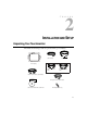
CHAPTER 2 INSTALLATION AND SETUP CHAPTER2 Unpacking Your Touchmonitor Check that the following 9 items are present and in good condition: OSD Remote Video cable LCD Display OR USB touchscreen cable Serial touchscreen cable Monitor power cable (US/Canada) Elo Quick Install Guide European monitor power cable CD Software Quick Install Guide and software CD Mounting brackets (2) 2-3
Product Overview (1545L) Main Unit LCD Display Detachable mounting L-brackets Rear View 2-4 Elo Entuitive Touchmonitor User Guide
Bottom View/Side View Power switch Touch interface serial Video cable connector Remote OSD connector Power connector Product Overview (1547L/1548L/1549L) Main Unit 2-5
Rear View 75 75 Side View Power switch Touch interface serial 2-6 Video cable connector Elo Entuitive Touchmonitor User Guide Remote OSD connector Power connector
Product Overview (1567L) Main Unit Rear View 75 75 2-7
Side View Power switch Touch interface serial 2-8 Video cable connector Elo Entuitive Touchmonitor User Guide Remote OSD connector Power connector
Attaching the L-Brackets Depending on your mounting scheme, use the L-brackets or the VESA 75mm standard holes located on the back of the kiosk monitor. See page 15 for VESA mounting information. NOTE: You will need a screwdriver to attach the L-brackets. Your kiosk touchmonitor comes with a mounting bracket (C-bracket) attached at the back. Included are two L-brackets (and four screws) that attach to both ends of the C-bracket for additional mounting options.
Touch Interface Connection NOTE: Your interface cables may have been pre-connected to your monitor at the factory. Your touchmonitor comes with one of the following touchscreen connector cables: Serial (RS-232) cable or USB cable (For Windows 98 or Windows 2000 computers only.) To setup this display, please refer to the following figures and procedures: Serial Connection The following illustrations guide you step by step in connecting your touchmonitor using a serial cable connection.
Connecting the Video Cable Connections on underside Female 15-pin video connector Video cable Video port • Connect the 15-pin video cable to the video port on your PC. • Connect the other end of the video cable to the video connector on your touchmonitor. • Secure the cable to your touchmonitor and PC by turning the screws on the connector clockwise.
Connecting the Serial Touchscreen Cable Connections on underside Serial touchscreen cable Serial touchscreen cable • Connect the female end of the serial (RS-232) cable to the serial port on the back of your PC. • Connect the male end of the cable to the serial touchscreen connector on your touchmonitor. • Secure the cable to your touchmonitor and PC by turning the screws on the connector.
Connect the Remote OSD Cable Connections on underside OSD remote port Video cable Video port Ferrite bead • Connect the 6 pin DIN cable to the OSD Remote port on your touchmonitor.
Connecting the Power Cable Connections on underside Power Cable Power cable Depending on where you live, you will use either the European or US/Canadian power cable. • Connect the female end of the power cable into the power port on the touchmonitor. NOTE: To protect your equipment against risk of damage from electrical surges in the power line, plug the touchmonitor’s power cord into a surge protector, and then connect the surge protector to a grounded (three-pronged) AC electrical outlet.
USB Connection NOTE: A USB connection can only be used if your PC is running Windows 98 or Windows 2000. The following illustrations guide you step by step in connecting your touchmonitor using a USB cable connection. Before connecting the cables to your touchmonitor and PC, be sure that the computer and the touchmonitor are turned off.
Connecting the Video Cable Connections on underside Female 15-pin video connector Video cable Video port • Connect the 15-pin video cable to the video port on your PC. • Connect the other end of the video cable to the video connector on your touchmonitor. • Secure the cable to your touchmonitor and PC by turning the screws on the connector clockwise.
Connecting the USB Touchscreen Cable Connections on underside USB touchscreen connector USB touchscreen cable • Connect the USB touchscreen cable to the USB touchscreen connector on the touchmonitor. • Connect the other end of the USB cable to your PC. • The touchscreen cable connectors should fit snugly into the connectors on your touchmonitor and PC.
Connecting the Remote OSD Cable Connections on underside OSD Remote Port Video cable Video port Ferrite bead • Connect the 6 pin DIN cable to the OSD Remote port on your touchmonitor.
Connecting the Power Cable Connections on underside Power Cable Power cable Depending on where you live, you will use either the European or US/Canadian power cable. • Connect the female end of the power cable into the power port on the touchmonitor. NOTE: To protect your equipment against risk of damage from electrical surges in the power line, plug the touchmonitor’s power cord into a surge protector, and then connect the surge protector to a grounded (three-pronged) AC electrical outlet.
Optimizing the LCD Display To ensure the LCD display works well with your computer, configure the display mode of your graphic card to make it less than or equal to 1024 x 768 resolution, and make sure the timing of the display mode is compatible with the LCD display. Refer to Appendix A for more information about resolution. Compatible video modes for your touchmonitor are listed in Appendix C.
Installing the Driver Software Elo TouchSystems provides driver software that allows your touchmonitor to work with your computer. Drivers are located on the enclosed CD-ROM for the following operating systems: • Windows XP • Windows 2000 • Windows Me • Windows 98 • Windows 95 • Windows NT 4.0 Additional drivers and driver information for other operating systems (including MS DOS, Windows 3.x, OS/2, Macintosh and Linux) are available on the Elo TouchSystems web site at www.elotouch.com.
Installing the Serial Touch Driver for Windows XP, Windows 20001, Me, 95/98 and NT 4.0 NOTE: For Windows 2000 and NT 4.0 you must have administrator access rights to install the driver. 1 Insert the Elo CD-ROM in your computer’s CD-ROM drive. If the AutoStart feature for your CD-ROM drive is active, the system automatically detects the CD and starts the setup program. 2 Follow the directions on the screen to complete the driver setup for your version of Windows.
Installing the Serial Touch Driver for MS-DOS and Windows 3.1 To install Windows 3.x and MS-DOS from Windows 95/98, follow the directions below: 1 Insert the Elo CD-ROM in your computer’s CD-ROM drive. 2 From DOS, type d:\EloDos_W31 to change to the correct directory on the CD-ROM (your CD-ROM drive may be mapped to a different drive letter). 3 Type install and press Enter to start the installation. 4 Align the touchscreen. You must have already completed Steps 1 and 2 before proceeding.
Installing the USB Touch Driver Installing the USB Touch Driver for Windows 98 and Windows 2000 1 Insert the Elo CD-ROM in your computer’s CD-ROM drive. If Windows 98 or Windows 2000 starts the Add New Hardware Wizard: 2 Choose Next. Select “Search for the best driver for your device (Recommended)” and choose Next. 3 When a list of search locations is displayed, place a checkmark on “Specify a location” and use Browse to select the \EloUSB directory on the Elo CD-ROM. 4 Choose Next.
CHAPTER 3 OPERATION CHAPTER3 About Touchmonitor Adjustments Your touchmonitor will likely require adjustment. Variations in video output and application will require you to adjust your touchmonitor to optimize the quality of the display. For best performance, your monitor should be operating in native resolution, that is 1024 x 768 at 60-75 Hz. Use the Display control panel in Windows to choose 1024 x 768 resolution. Operating in other resolutions will degrade video performance.
Remote OSD Buttons AUTO/SEL DOWN UP AUTO/SEL DOWN 4 UP MENU 2 1 5 Control Function Display Exits the OSD menus. 1 MENU Menu 2 UP Contrast/ Plus/Clockwise 3 DOWN Brightness/Minus/ Counter-Clockwise AUTO/SEL Auto/Select Select- To select the adjustment items from the OSD menus. Auto- To activate the “Auto Adjustment” function to obtain an optimum image. Power Switch Switches on/off the power of your touchmonitor. Enable/Disable 1.
OSD Menu Function CONTRAST 50 Contrast Phase Controls the picture contrast Controls the vertical fine adjustment Brightness Clock Controls the picture brightness Controls the horizontal fine adjustment V-Position OSD H-Position Controls the vertical position Adjusts the horizontal position of the OSD menu H-Position OSD V-Position Controls the horizontal position Adjust the vertical position of the OSD menu Recall Defaults OSD Time Recalls factory settings of the image parameters Determ
3-28 Elo Entuitive Touchmonitor User Guide
CHAPTER 4 TROUBLESHOOTING CHAPTER4 If you are experiencing trouble with your touchmonitor, refer to the following table. If the problem persists, please contact your local dealer or our service center. Solutions to Common Problems Problem Suggestion(s) No image appears on screen. Check that all the I/O and power connectors are properly connected as described in Chapter 2. Make sure the pins of the connectors are not crooked or broken.
4-30 Image has vertical flickering line bars. Use “PHASE” to make an adjustment. Check and reconfigure the display mode of the vertical refresh rate of your graphic card to make it compatible with the LCD display. Image is unstable and flickering Use “CLOCK” to make an adjustment. Image is scrolling Make sure the VGA signal cable (or adapter) is well connected. Check and reconfigure the display mode of the vertical refresh rate of your graphic card to make it compatible with the LCD display.
APPENDIX A NATIVE RESOLUTION CHAPTER4 The native resolution of a monitor is the resolution level at which the LCD panel is designed to perform best. For the Elo LCD touchmonitor, the native resolution is 1024 x 768 for the XGA-15 inch size. In almost all cases, screen images look best when viewed at their native resolution. You can lower the resolution setting of a monitor but not increase it.
As an example, a SVGA resolution LCD panel has 800 pixels horizontally by 600 pixels vertically. Input video is also represented by the same terms. XGA input video has a format of 1024 pixels horizontally by 768 pixels vertically. When the input pixels contained in the video input format match the native resolution of the panel, there is a one to one correspondence of mapping of input video pixels to LCD pixels.
APPENDIX B TOUCHMONITOR SAFETY CHAPTER 4 This manual contains information that is important for the proper setup and maintenance of your touchmonitor. Before setting up and powering on your new touchmonitor, read through this manual, especially Chapter 2 (Installation), and Chapter 3 (Operation). 1 To reduce the risk of electric shock, follow all safety notices and never open the touchmonitor case.
Care and Handling of Your Touchmonitor The following tips will help keep your Elo Entuitive touchmonitor functioning at the optimal level. • To avoid risk of electric shock, do not disassemble the brick supply or display unit cabinet. The unit is not user serviceable. Remember to unplug the display unit from the power outlet before cleaning. • Do not use alcohol (methyl, ethyl or isopropyl) or any strong dissolvent. Do not use thinner or benzene, abrasive cleaners or compressed air.
APPENDIX C TECHNICAL SPECIFICATIONS CHAPTER4 Compatibility Modes Your Elo Entuitive touchmonitor is compatible with the following video modes: Mode Resolution H. Frequency (kHz) V. Frequency (Hz) IBM & VESA VGA IBM & VESA VGA 640 x 350 640 x 400 31.47 31.47 70.09 70.09 IBM & VESA VGA IBM & VESA VGA 720 x 400 640 x 480 31.47 31.47 70.09 59.94 IBM & VESA VGA IBM & VESA VGA VESA VGA 640 x 480 640 x 480 800 x 600 37.86 37.50 35.16 72.81 75.00 56.25 VESA VGA VESA VGA 800 x 600 800 x 600 37.
Touchmonitor Specifications ET1545L/1547L/1548L/1567L Table C.1 15" LCD Touchmonitor Specifications Size Active matrix, thin film transistor (TFT), liquid crystal display 15-inch diagonal 304 x 228 mm useful screen area Pixel Format 1024 x 768 Touchscreen 0.125-inch IntelliTouch and SecureTouch, anti-glare Surface wave technology Colors 16 million with dithering Display Brightness IntelliTouch: 270 cd/m² Max.
Touchmonitor Specifications ET1549L Table C.2 15" LCD Touchmonitor Specifications Size Active matrix, thin film transistor (TFT), liquid crystal display 15-inch diagonal 308 x 232 mm useful screen area Pixel Format 1024 x 768 Touchscreen 0.125-inch IntelliTouch Surface wave technology Colors 262,144 Display Brightness IntelliTouch: 225 cd/m² Max.
Table C.3 IntelliTouch Touchmonitor Specifications Mechanical Positional Accuracy Standard deviation of error is less than 0.080 in. (2.03 mm). Equates to less than ±1%. Touchpoint Density Touch Activation Force Surface Durability Expected Life Performance More than 100,000 touchpoints/in2 (15,500 touchpoints/cm2). Sealing Typically less than 3 ounces (85 grams). Surface durability is that of glass, Mohs’ hardness rating of 7.
Table C.4 SecureTouch Touchmonitor Specifications Mechanical Positional Accuracy Standard deviation of error is less than 0.080 in. (2.03 mm). Equates to less than ±1%. Touchpoint Density Touch Activation Force Surface Durability Expected Life Performance More than 100,000 touchpoints/in2 (15,500 touchpoints/cm2). Typically less than 3 ounces (85 grams). Surface durability is that of glass, Mohs’ hardness rating of 7. No known wear-out mechanism, as there are no layers, coatings, or moving parts.
15" LCD Touchmonitor Dimensions ET1545L C-40 Elo Entuitive Touchmonitor User Guide
See www.elotouch.com/pdfs/drawings/ms500235.pdf ET1547L/1548L/1549L 313 R5.4 9 4.
1 See detail A A=28 Detail A Scale 2:1 90 115 65 460 380 75 70 56 C-42 Elo Entuitive Touchmonitor User Guide 75 77 296
ET1567L 400 305 4.
75 75 65 86 Cut Out Dimensions ET1545L Front Mount Cut Out See www.elotouch.com/pdfs/drawings/ms500108.pdf for more information.
ET1545L Rear Mount Cut Out ET1547L/1548L/1549L Rear Mount Plate Cut Out 157 314.0 +1.0 0 4X R4.00 70 119 238.0 +1.0 0 4X Customer Option See notes 440 NOTES: Material: 1. Wood: 04.5 holes thru for M4 screws w/nuts or screws for wood 04 mm. 2. Sheet Metal: Concealed head threaded studs M4 w/nuts.
ET1567L Front Mount Plate Cut Out 157 314.0 +1.0 0 4X R4.00 119 70 4X Customer Option See notes 440 NOTES: Material: 1. Wood: 04.5 holes thru for M4 screws w/nuts or screws for wood 04 mm. 2. Sheet Metal: Concealed head threaded studs M4 w/nuts. C-46 Elo Entuitive Touchmonitor User Guide 238.0 +1.
REGULATORY INFORMATION CHAPTER4 I. Electrical Safety Information: A) Compliance is required with respect to the voltage, frequency, and current requirements indicated on the manufacturer’s label. Connection to a different power source than those specified herein will likely result in improper operation, damage to the equipment or pose a fire hazard if the limitations are not followed. B) There are no operator serviceable parts inside this equipment.
This equipment has been tested to the requirements for the CE Mark as required by EMC Directive 89/336/EEC indicated in European Standard EN 55 022 Class B and the Low Voltage Directive 73/23/EEC as indicated in European Standard EN 60 950. D) General Information to all Users: This equipment generates, uses and can radiate radio frequency energy. If not installed and used according to this manual the equipment may cause interference with radio and television communications.
"The application of this monitor is restricted to special controlled luminous environments. The screen surface trend to reflect annoying light of lamps and sunlight. To avoid these reflections the monitor should not be positioned in front of a window or directed to luminaries. The monitor is in compliance with Reflection Class III according to ISO 9241-7" “Die Anwendung dieses Bildschirms ist auf speziel kontrollierte Umgebungsbeleuchtungen eingeschränkt.
50 Elo Entuitive Touchmonitor User Guide
WARRANTY CHAPTER4 Except as otherwise stated herein or in an order acknowledgment delivered to Buyer, Seller warrants to Buyer that the Product shall be free of defects in materials and workmanship. The warranty for the touchmonitors and components of the product are: 3 years monitor, 10 years IntelliTouch screen, 5 years Accu- Touch screen, 5 years Controller. Seller makes no warranty regarding the model life of components.
THESE REMEDIES SHALL BE THE BUYER’S EXCLUSIVE REMEDIES FOR BREACH OF WARRANTY. EXCEPT FOR THE EXPRESS WARRANTY SET FORTH ABOVE, SELLER GRANTS NO OTHER WARRANTIES, EXPRESS OR IMPLIED BY STATUTE OR OTHERWISE, REGARDING THE PRODUCTS, THEIR FITNESS FOR ANY PURPOSE, THEIR QUALITY, THEIR MERCHANTABILITY, THEIR NONINFRINGEMENT, OR OTHERWISE. NO EMPLOYEE OF SELLER OR ANY OTHER PARTY IS AUTHORIZED TO MAKE ANY WARRANTY FOR THE GOODS OTHER THAN THE WARRANTY SET FORTH HEREIN.
Index Numerics 15" LCD Touchmonitor Dimensions, 40 15” LCD Touchmonitor (ET15-XXWC-1) Specifications, 36, 37 A About the Product, 1 About Touchmonitor Adjustments, 25 Attaching the L-Brackets, 9 Auto Adjust, 27 B Image, unstable, 30 Image, vertical flickering, 30 Installation and Setup, 3 Installing the Driver Software, 21 Installing the Serial Touch Driver for MS-DOS and Windows 3.1, 23 Installing the Serial Touch Driver for Windows XP, Windows 2000, Me, 95/98 and NT 4.
S Troubleshooting, 29 SecureTouch Touchmonitor Specifications, 39 Serial Connection, 10 Side View (1547L/1548L/1549L), 6 Side View (1567L), 8 Solutions to Common Problems, 29 U Unpacking Your Touchmonitor, 3 USB Connection, 15 Using the On-Screen Display Menus, 25 T V Technical Specifications, 35 Touch Interface Connection, 10 Touch not working, 30 Touchmonitor Safety, 33 Touchmonitor Specifications ET1545L/1547L/1548L/ 1567L, 36 Touchmonitor Specifications ET1549L, 37 VESA Mount on Your Touchmonitor