Elo Entuitive Touchmonitor User Guide For 15” and 17” CRT Rear Mount Touchmonitors Version 1.0 DOC# SW500127 P/N 008527 ET1545C Series Models ET1745C Series Models Elo TouchSystems, Inc. 1-800-ELOTOUCH www.elotouch.
Copyright © 2000 Elo TouchSystems Inc. All Rights Reserved. No part of this publication may be reproduced, transmitted, transcribed, stored in a retrieval system, or translated into any language or computer language, in any form or by any means, including, but not limited to, electronic, magnetic, optical, chemical, manual, or otherwise without prior written permission of Elo TouchSystems. Disclaimer The information in this document is subject to change without notice.
iv-Elo Entuitive Touchmonitor CRT Desktop User Guide
Contents Chapter 1. Introduction ........................................................................1 Precautions................................................................................................1 About the Product .....................................................................................1 Chapter 2. Installation and Setup ........................................................3 Unpacking Your Touchmonitor................................................................
Contents Appendix C. Technical Specifications..................................................29 Touchmonitor Specifications ...................................................................30 IntelliTouch Touchmonitor Specifications ..............................................32 AccuTouch Touchmonitor Specifications ...............................................34 Signal PINOUT for 15” and 17” Monitors ..........................................36 Power Consumption....................................
Precautions Chapter 1 Introduction Congratulations on your purchase of an Elo TouchSystems Entuitive touchmonitor. Your new high-resolution touchmonitor combines the reliable performance of Elo’s touch technology with the latest advances in CRT display design. This combination of features creates a natural flow of information between a user and the touchmonitor. Precautions Follow all warnings, precautions and maintenance as recommended in this user’s manual to maximize the life of your unit.
Chapter 1 : Introduction 2 - Elo Entuitive Touchmonitor CRT Rear Mount User Guide
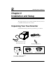
Unpacking Your Touchmonitor Chapter 2 Installation and Setup This chapter discusses how to install your CRT touchmonitor and how to install Elo TouchSystems driver software.
Chapter 2 : Installation and Setup Getting Started Selecting a Suitable Location ❑ Place the monitor at least 12 inches from other electrical or heat-emitting equipment and allow at least 4 inches on each side for ventilation. ❑ Place the monitor in a position where no light shines or is reflected directly on the screen. ❑ To reduce eye strain, avoid installing the monitor unit against a bright background such as a window. ❑ Position the monitor so the top of the screen is no higher than eye level.
Mounting Your Touchmonitor Mounting Your Touchmonitor Your Elo touchmonitor is designed to be mounted in a variety of ways. The mounting brackets enable you to mount your touchmonitor horizontally or vertically. You can also use the keyholes on the bottom of the monitor for slide-in-place mounting. See Appendix C for dimension drawings of all mounting options. Note: You will need a Phillips screwdriver to attach the L-brackets.
Chapter 2 : Installation and Setup Vertical Mount To mount the brackets vertically to your touchmonitor: 1. Locate the two holes on each side of your touchmonitor. Match up the two holes of one bracket to the holes on one side of your touchmonitor. L-bracket 2. Place two screws in the holes and with the screwdriver, screw them in to secure the bracket. 3. Repeat steps 1 and 2 to attach the other L-bracket to the other side of the touchmonitor.
Connecting Your Touchmonitor Connecting Your Touchmonitor Your touchmonitor comes with one of the following touchscreen connector cables: Serial (RS-232) or USB cable (for Windows 98 and Windows 2000 systems only). IMPORTANT: Before connecting the cables to your touchmonitor and PC, be sure that the computer and touchmonitor are turned off. 1. Connect the video cable to the video connector on your PC. Secure the cable to your PC by turning the screws on the connector.
Chapter 2 : Installation and Setup 2. Connect the power cable to the AC connector on your touchmonitor. To protect your equipment against risk of damage from electrical surges in the power line, plug the touchmonitor’s power cord into a surge protector, and then connect the surge protector to a grounded (three-pronged) AC electrical outlet.
Connecting Your Touchmonitor 3. Connect the touchscreen cable. Determine if you have RS-232 or USB. Connect one end to the appropriate port on the back of your PC. Connect the other end of the cable to the touchscreen connector on your touchmonitor. Secure the serial cable to your touchmonitor and PC by turning the screws on the connector. The USB cable connectors should fit snugly into the connectors on your PC and touchmonitor.
Chapter 2 : Installation and Setup 4. The OSD controls and the Soft Power switch are located on a panel inside the bottom of your monitor. Power on your monitor using the Soft power switch and check that the power LED is on, then power on your PC. If the LED is not on, repeat steps 2, 3, and 4, or refer to Chapter 4, Troubleshooting. Underside view of the touchmonitor Menu Brightness Select Power LED Contrast Soft Power Switch 5. After a brief pause the picture should appear.
Installing the Driver Software Installing the Driver Software Elo TouchSystems provides driver software that allows your touchmonitor to work with your computer. Drivers are located on the enclosed CDROM for the following operating systems: ❑ Windows 2000 ❑ Windows 98 ❑ Windows 95 ❑ Windows NT 4.0 Additional drivers and driver information for other operating systems (including MS DOS, Windows 3.x, OS/2, Macintosh and Linux) are available on the Elo TouchSystems web site at www.elotouch.com.
Chapter 2 : Installation and Setup 2. Click the Browse button to locate the EloCd.exe program on the CD-ROM. 3. Click Open, then OK to run EloCd.exe. 4. Follow the directions on the screen to complete the driver setup for your version of Windows. Installing the USB Touch Driver for Windows 2000 and Windows 98 1. Insert the Elo CD-ROM in your computer’s CD-ROM drive. If Windows 98 or Windows 2000 starts the Add New Hardware Wizard: 2. Choose Next.
Installing the Driver Software 2. Click the Browse button to locate the EloCd.exe program on the CD-ROM. 3. Click Open, then OK to run EloCd.exe. 4. Follow the directions on the screen to complete the driver setup for your version of Windows.
Chapter 2 : Installation and Setup 14 - Elo Entuitive Touchmonitor CRT Rear Mount User Guide
About Touchmonitor Adjustments Chapter 3 Operation About Touchmonitor Adjustments By design, your Elo Entuitive touchmonitor should not require any adjustments. The factory settings will give you optimum video results with most standard PC video display adapters. However, after connecting your touchmonitor you can further optimize the settings to meet your requirements by following the directions in this chapter.
Chapter 3 : Operation Touchmonitor Controls You can adjust the screen display by using the control buttons located on a panel that’s inside the bottom of your touchmonitor.
Touchmonitor Controls Using the On Screen Display (OSD) The 3rd and 4th buttons (Brightness/ function: and Contrast/ ) have a dual Brightness Use the Brightness/ button to select the brightness adjustment and to decrease the value of a selection. Contrast Use the Contrast/ button to select the contrast adjustment and to increase the value of a selection. To use the OSD: 1. Push the Menu button to access the OSD. The resolution and frequency are displayed at the top of the menu for your information. 2.
Chapter 3 : Operation OSD Adjustments H. Size Adjusts the horizontal size of the entire screen image. H. Position Adjusts the horizontal position of the entire screen image. V. Size Adjusts the vertical size of the entire screen image. V. Position Adjusts the vertical position of the entire screen image. Pincushion If the vertical sides of the picture curve in or bulge out, you can correct the distortion by using the pincushion adjustment.
Touchmonitor Controls H. Moire Clears horizontal moire if a series of concentric circles or arcs appear on your screen. Language You can select the language in which adjustment menus are displayed. The following languages are available; English, German, French, Italian, Spanish, Swedish, Finnish, Danish, and Portuguese. Rotation If the entire screen image is tilted, you can correct the distortion by using the rotation adjustment. OSD H.
Chapter 3 : Operation Degauss External magnetic fields may cause distortion or discoloration in the picture. Demagnetizing takes place automatically when the display unit is switched on, and the unit normally maintains faultless color purity during operation. If you have tilted, swiveled or moved the display unit, you can perform demagnetization. During the process the picture is distorted for a few seconds. After demagnetization, the color impurities have disappeared if caused by stray magnetic fields.
Chapter 4 Troubleshooting Problem No picture. Suggestion (s) Your touchmonitor may not be getting power. Make certain that your power strip is plugged into the wall socket and that the PC and touchmonitor are plugged in and powered on. Test the power supply by trying different cables or a different wall outlet, or by plugging another appliance into the outlet. The touchmonitor might be in standby mode. Push one of the keyboard keys. Check that the keyboard is properly connected to the computer.
Chapter 4 : Troubleshooting Problem Suggestion (s) Duplicated images A problem with your graphics adapter or touchmonitor. Contact your service representative. Touch doesn’t work. Check to make sure the touchscreen cable is securely attached at both ends.
Monitor Warning Messages Message Suggestion Error message: OUT OF RANGE The graphics adapter is set for a refresh rate or a line frequency that is too high. Select another display mode with lower frequencies as directed by your video card vendor. Self diagnostics message: NO SIGNAL This message indicates that the signal is missing or faulty. Check that the signal cable connector is properly connected and that the connection pins are not bent or damaged.
Chapter 4 : Troubleshooting 24 - Elo Entuitive Touchmonitor CRT Rear Mount User Guide
Touchscreens: An Overview Appendix A Touch Technology Touchscreens: An Overview Typically, users communicate with computers by using a mouse, a keyboard, or a combination of the two. Users who are not keyboard-literate or mouse-savvy can become frustrated with how long human-to-computer interactions take. Computer literacy is learned. This is complicated by the fact that using a keyboard or a mouse is neither intuitive nor natural for most people.
Appendix A : Touch Technology For example, a customer in a department store could scroll through a product catalog by increasing or decreasing pressure on an icon. IntelliTouch’s pressure sensitivity increases the intuitive nature of a user/ touchscreen interaction by allowing for increased selectivity.
Appendix B Touchmonitor Safety This manual contains information that is important for the proper setup and maintenance of your touchmonitor. Before setting up and powering on your new touchmonitor, read through this manual, especially Chapter 2, Installation and Setup, and Chapter 3, Operation. 1. To reduce the risk of electric shock, follow all safety notices and never open the touchmonitor case. 2. Your new touchmonitor is equipped with a three-wire, grounding power cord.
Appendix B : Touchmonitor Safety Care and Handling of Your Touchmonitor The following tips will help keep your Elo Entuitive touchmonitor functioning at the optimal level. ❑ To avoid risk of electric shock, do not disassemble the display unit cabinet. The unit is not user serviceable. Remember to unplug the display unit from the power outlet before cleaning. ❑ Do not use alcohol (methyl, ethyl or isopropyl) or any strong dissolvent. Do not use thinner or benzene, abrasive cleaners or compressed air.
Appendix C Technical Specifications Note: All specifications are subject to change.
Appendix C : Technical Specifications Touchmonitor Specifications 17” Monitor 15” Monitor Picture Tube 17” (15.7” diagonal viewable image), 0.27-mm dot pitch, anti-static, anti-glare, and TCO treatment coated. 15” (13.8” diagonal viewable image), 0.28-mm dot pitch, anti-static, anti-glare, and multiple layer coating.
Touchmonitor Specifications 15” Monitor 17” Monitor On-Screen Adjustments H/V POSITION, H/V SIZE, PINCUSHION, TRAPEZIOD, PARALLEL, PIN BALANCE, H/V MOIRE, LANGUAGES, ROTATION, OSD H/V POSITION, COLOR CONTROL, RECALL, INFORMATION, DEGAUSS, BRIGHTNESS, CONTRAST H/V POSITION, H/V SIZE, PINCUSHION, TRAPEZIOD, PARALLEL, PIN BALANCE, H/V MOIRE, LANGUAGES, ROTATION, OSD H/V POSITION, COLOR CONTROL, RECALL, INFORMATION, DEGAUSS, BRIGHTNESS, CONTRAST Safety Regulations UL, cUL, DHHS, TÜVGS UL, cUL, DHHS, TÜVG
Appendix C : Technical Specifications IntelliTouch Touchmonitor Specifications Mechanical Positional Accuracy Standard deviation of error is less than 0.080 in. (2.03 mm). Equates to less than ±1%. Touchpoint Density More than 100,000 touchpoints/in2 (15,500 touchpoints/cm2). Touch Activation Force Typically less than 3 ounces (85 grams). Surface Durability Surface durability is that of glass, Mohs’ hardness rating of 7.
Touchmonitor Specifications Environmental Chemical Resistance The active area of the touchscreen is resistant to all chemicals that do not affect glass, such as: Acetone Toluene Methyl ethyl ketone Isopropyl alcohol Methyl alcohol Ethyl acetate Ammonia-based glass cleaners Gasoline Kerosene Vinegar Electrostatic Protection (per EN 61 000-4-2, 1995) Meets Level 4 (15 kV air/8 kV contact discharges).
Appendix C : Technical Specifications AccuTouch Touchmonitor Specifications Mechanical Construction Top: Polyester with outside hard-surface coating with clear or antiglare finish. Inside: Transparent conductive coating. Bottom: Glass substrate with uniform resistive coating. Top and bottom layers separated by Elo-patented separator dots. Positional Accuracy Standard deviation of error is less than 0.080 in. (2.03 mm). This equates to less than ±1%.
Touchmonitor Specifications Environmental Chemical Resistance The active area of the touchscreen is resistant to the following chemicals when exposed for a period of one hour at a temperature of 21°C: Acetone Methylene chloride Methyl ethyl ketone Isopropyl alcohol Hexane Turpentine Mineral spirits Unleaded gasoline Diesel fuel Motor oil Transmission fluid Antifreeze Elo Entuitive Touchmonitor CRT Rear Mount User Guide - 35
Appendix C : Technical Specifications Signal PINOUT for 15” and 17” Monitors 5 4 10 15 3 9 14 2 8 13 1 7 12 6 11 PIN Signal Num ber 1 Red video 2 Green video 3 Blue video 4 Ground 5 *V GA card detection (GND) 6 Red return 7 Green return 8 Blue return 9 +5 V 10 Sync return 11 Ground 12 SDA (Serial Data) 13 Horizontal Sync 14 V ertical Sync 15 SCL (Serial Clock) *Pin 5, self-test pin shall be grounded when signal connector is plugged in.
Power Consumption Power Consumption The touchmonitor comes with a power-saving feature that controls its power consumption. This feature complies with both the EPA’s Energy Star requirements and European NUTEK/TCO’s power management guidelines. It also conforms to the Display Power Management System (DPMS) power-down signaling method approved by the Video Electronics Standard Association (VESA) 15” Monitor Mode LED Power consumption (W) Normal Green 75 Standby Green/Orange blinking (1 sec.
Appendix C : Technical Specifications Preset Timing Table Your Elo Entuitive touchmonitor has 8 preset timing modes. The following are modes preset as factory defaults: No. Resolution Horizontal Frequency Refresh Rate 1 720x400 31.5 kHz 70 Hz 2 640x480 43.3 kHz 85 Hz 3 640x480 50.6 kHz 100 Hz 4 800x600 46.9 kHz 75 Hz 5 800x600* 53.7 kHz 85 Hz 6 800x600 63.9 kHz 100 Hz 7 1024x768 60.0 kHz 75 Hz 8 1024x768* 68.
Regulatory Information Electrical Safety Information A) Compliance is required with respect to the voltage, frequency, and current requirements indicated on the manufacturer’s label. Connection to a different power source than those specified herein will likely result in improper operation or damage to the equipment, or may pose a fire hazard if the limitations are exceeded. B) There are no operator serviceable parts inside this equipment.
b) To ensure compliance, use only the provided manufacturer-approved line cord. c) The user is cautioned that changes or modifications to the equipment not expressly approved by the party responsible for compliance could void the user’s authority to operate the equipment. 2) If this equipment appears to cause interference with radio or television reception, or any other device: a) Verify as an emission source by turning the equipment off and on.
Warranty Except as otherwise stated herein or in an order acknowledgment delivered to Buyer, Seller warrants to Buyer that the Product shall be free of defects in materials and workmanship. See relevant specification sheet for touchmonitors. Seller makes no warranty regarding the model life of monitors. Seller’s suppliers may at any time and from time to time make changes in the monitors delivered as Products or components.
MENT, OR OTHERWISE. NO EMPLOYEE OF SELLER OR ANY OTHER PARTY IS AUTHORIZED TO MAKE ANY WARRANTY FOR THE GOODS OTHER THAN THE WARRANTY SET FORTH HEREIN. SELLER’S LIABILITY UNDER THE WARRANTY SHALL BE LIMITED TO A REFUND OF THE PURCHASE PRICE OF THE PRODUCT. IN NO EVENT SHALL SELLER BE LIABLE FOR THE COST OF PROCUREMENT OR INSTALLATION OF SUBSTITUTE GOODS BY BUYER OR FOR ANY SPECIAL, CONSEQUENTIAL, INDIRECT, OR INCIDENTAL DAMAGES.
Index INDEX H. Size ● 18 Haze ● 34 Horizontal Mount ● 5 Humidity ● 31 15 ● 38 15” and 17” CRT Rear Mount Touchmoni- I tor Dimensions ● 38 Information ● 19 Input Signal ● 30 A Input Voltage ● 30 About the Product ● 1 Installation ● 3 About Touchmonitor Adjustments ● 15 Installing the Driver Software ● 11 AccuTouch Touchmonitor Specifications ● Installing the Serial Touch Driver for Win34 dows 2000, 95/98 and NT 4.
Index Precautions ● 1 Preset Modes ● 37 Preset Timing Table ● 38 R Recall ● 19 Regulatory Information ● 39 Rotation ● 19 Touchmonitor Controls ● 16 Touchmonitor Safety ● 27 Touchmonitor Specifications ● 30 Touchpoint Density ● 32, 34 Touchscreens An Overview ● 25 Trapezoid ● 18 Troubleshooting ● 21 U S Unpacking Your Touchmonitor ● 3 Safety Regulations ● 31 Using the On Screen Display (OSD) ● 17 Sealing ● 32 Selecting a Suitable Location ● 4 Signal PINOUT for 15” and 17” Monitors ● V V. Moire ● 18 36 V.