Elo Entuitive Touchcomputer User Guide ESY1529L Elo Entuitive ESY1529L Touchcomputer Series Revision C
Elo Entuitive Touchcomputer User Guide 15.0" LCD Desktop Touchcomputer ESY1529L Touchcomputer Series Revision C P/N 008606E Elo TouchSystems, Inc. 1-800-ELOTOUCH www.elotouch.
Copyright © 2005 Elo TouchSystems Inc. All Rights Reserved. No part of this publication may be reproduced, transmitted, transcribed, stored in a retrieval system, or translated into any language or computer language, in any form or by any means, including, but not limited to, electronic, magnetic, optical, chemical, manual, or otherwise without prior written permission of Elo TouchSystems. Disclaimer The information in this document is subject to change without notice.
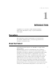
Table of Contents Chapter 1 Introduction Chapter 3 1 Precautions ......................................................... 1 About the Product ............................................... 1 Operating System ............................................ 2 Windows XP and 2000 ................................ 2 Windows CE ................................................ 2 Customer Display ............................................ 2 Magnetic Stripe Reader (MSR) ................... 2 Touchscreen .........
Humidity .............................................................. 33 Altitude ................................................................
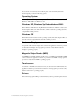
C H A P T E R 1 INTRODUCTION Congratulations on your purchase of an Elo TouchSystems Entuitive Touchcomputer. This manual is to help you operate and maintain the Touchcomputer. Precautions Follow all warnings, precautions and maintenance as recommended in this user’s manual to maximize the life of your unit. See Appendix B for more information on touchmonitor safety.
mouse and an on-screen keyboard to take the place of an external keyboard. The Touchcomputer provides the following options: Operating System ® ® ® ® ® Microsoft Windows XP Professional, Microsoft Windows XP Embedded, Microsoft ® ® ® Windows 2000, Microsoft Windows CE. Windows XP, Windows Xp Embedded and 2000 When Windows XP, Windows Xp Embedded and Windows 2000 are selected, the Touchcomputer will boot from the hard drive, which contains the operating system. No compact flash will be provided.
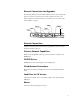
External Connections and Upgrades The following drawing shows the Touchcomputer external connector panel. This panel of connectors is used by the user to make external connections to the Touchcomputer. No external connections, other than power, are needed for the Touchcomputer to operate.
Keyboard • A keyboard can be added using the keyboard port. Upgrades and Changes A laptop type hard drive can be added internally to the CE version of the Touchcomputer. • Compact Flash can be added (through the compact flash door in the back of the Touchcomputer) to the Touchcomputer on Windows XP, Windows Xp Embedded and Windows 2000 Touchcomputers.
• U.S. Power Cable • European Power Cable • Power Brick • Reinstall CD(s) with applicable operating systems(Windows 2000 or Windows XP) • No CD is provided for Windows CE (but the image is on the Touchcomputer CD.
1-6 Elo Entuitive Touchcomputer User Guide
C H A P T E R 2 TOUCHCOMPUTER SETUP Initial Turn On and Software Registration Touchcomputer Operating System Setup The initial setup of the Windows operating system takes approximately 5-10 minutes. Additional time may be needed depending on computer hardware configuration and connected devices. To setup the Windows OS for your computer, turn on your computer and follow the instructions on the screen. Testing Pre-installed Devices Touchcomputers come pre installed with several different hardware options.
Keyboard Card Reader Testing • Click on the “KB MSR TEST” icon. • Scan a credit card and ensure data scanned correctly by seeing applicable information on all three tracks from the credit card. HID Card Reader Testing • Click on the “HID MSR TEST” icon • Click on scan button • Scan a credit card and ensure data scanned correctly by seeing applicable information on all three tracks from the credit card. Converting MSR from HID to Keyboard Emulation 1. To convert from HID mode to Keyboard Emulation mode 1.
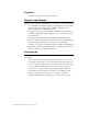
Controls There are two controls to operate the Touchcomputer. There is a brightness control and a volume control. To increase the brightness, press switch C. To decrease brightness, press switch D. To increase volume, press switch A. To decrease volume, press button B. The Touchcomputer has an On-Screen-Display (OSD) to indicate volume and brightness changes via an on-screen bar graph. Switch A Switch B Switch C Switch D Switch E Power To turn on the Touchcomputer, press switch E.
Technical Assistance There are three methods to obtain contact information for technical assistance on the Touchcomputer. • Touchcomputer itself • the Web • telephone These methods are described below. Using the Touchcomputer You can access the support information by going to the System Properties and clicking on the “Support Information” button.
C H A P T E R 3 SAFETY/SERVICING THE TOUCHCOMPUTER When servicing the computer perform the following: • Perform an orderly shutdown using the operating system menu. • Shut down the Touchcomputer and remove all external cables. • When opening the Touchcomputer, periodically touch any metal parts of the Touchcomputer, such as metal portions of the case or connector shells on the monitor. • Handle components and cards with care. Do not touch components on the cards.
3-12 Elo Entuitive Touchcomputer User Guide
C H A P T E R 4 TECHNICAL DESCRIPTION Block Diagram The block diagram of the Touchcomputer is shown below: LCD Inveter OSD Switch panel CN2 +12 V CN3/CN21 CN22 CN1 Optional Hard Drive Optional Compact Flash J7 USB1 Dual USB Port(500 ma) CN17 Dual USB Port(500 ma) CN13 Serial Port CN14 Serial Port J16 PS2 keyboard J17 PS2Mouse J12 PCMCIA J15 Ethemet Port CN7 Speakers CN5 Single Board Computer(SBC) CN3 CN2 Internal Internal USB +5 V Serial Port @1 amp Port CN2 Serial Port CN20
Mother Board Block Diagram MEMORY PC133/SDR VIA EDEN ESP 1G Hz PROCESSOR FSB VIA VT8606 TWISTER NORTHBRIDGE GRAPHICS CORE AND MEMORY CONTROLLER BOOT ROM REALTEK RTL8100C FAST ETHERNET CONTROLLER PCI VIA VT82C686B SOUTHBRIDGE PERIPHERAL CONTROLLER FAST ETHERNET SOUND KEYBOARD MOUSE HARD DRIVE 2 SERIAL PORTS 4 USB PORTS LCD DISPLAY 4-14 Elo Entuitive Touchcomputer User Guide WINDBOND W83977F I/O CONTROLLER 2 SERIAL PORTS TI PCI1410 PC CARD CONTROLLER PCMCIA
Connectors on Mother Board The connectors on mother board allows you to connect external devices such as keyboard, floppy disk drives, hard disk drives, printers, etc. The following table lists the connectors on mother board and their respective functions.
CN1, CN2: COM4 and COM3 Connectors Pin # Signal Name 1 2 DCD RXD 3 4 CTS GND 5 6 TXD RTS 7 8 DSR DTR CN3: +5V Connector Pin # 1 Signal Name +5V 2 Ground CN4: +5V AND +12V Connector Pin # Signal Name 1 2 +5V Ground 3 +12V CN6, CN9: USB Pin Header Pin # Signal Name 1 2 Ground USB- 3 4 USB+ Vcc CN10: Panel Inverter Power Connector Pin # 1 Signal Name +12V 2 3 Ground Bright Adj 4 5 Ground BKLT ON CN11: OSD Panel Board Connector Pin # 1 Signal Name Vol+ 2 3 VolBright+ 4 5 BrightGro
J7: Primary IDE Connectors Signal Name Reset IDE Host data 7 Host data 6 Host data 5 Host data 4 Host data 3 Host data 2 Host data 1 Host data 0 Ground DRQ0 Host IOW Host IOR IOCHRDY DACK0 IRQ14 ASDRAMess 1 ASDRAMess 0 Chip select 0 Activity Vcc Ground Pin # 1 3 5 7 9 11 13 15 17 19 21 23 25 27 29 31 33 35 37 39 41 43 CN13, CN14: COM1 and COM2 Serial Ports Signal Name Pin # DCD 1 RXD 2 TXD 3 DTR 4 GND 5 Pin # 2 4 6 8 10 12 14 16 18 20 22 24 26 28 30 32 34 36 38 40 42 44 Pin # 6 7 8 9 10 Signal Name Gro
USB1, USB2: USB Connectors Pin # Signal Name 1 Vcc 2 USB3 USB+ 4 Ground J9: System Fan Power Connector J9 is a 3-pin header for an optional fan. The fan must be a 12V fan. Pin # Signal Name 1 Ground 2 +12V 3 Rotation detection J11: 24-bit LVDS Connector (DF13-20) Signal Name Pin # TX02 Ground 4 TX16 5V/3.3V 8 TX310 TX212 Ground 14 TXC16 5V/3.
J16: PS/2 Keyboard Connector Pin Signal Name 1 Keyboard data 6 5 2 N.C. 4 3 3 GND 1 2 4 5V 5 Keyboard clock 6 N.C. J17: PS/2 Mouse Connector Pin Signal Name 1 Mouse data 2 N.C. 6 5 3 GND 4 3 4 5V 2 1 5 Mouse clock 6 N.C.
Computer Specifications Processor • VIA Eden 1000MHz low power CPU or equivalent Memory • RAM- 512 MB Green Function • APM 1.2 compliant Audio Function • Stereo one watt capability per channel Operating System • Support for WinCE.Net 4.2 Pro+ • Support for Windows Pro 2000 • Support for Windows Xp Pro Sp2 • Support for Windows Xp Embedded Ports • Four RS-232 Serial Ports. Two internal ports(CN1 and CN2) and 2 external ports (CN13 and CN14). • Connectors-External ports shall use standard DB9 connectors.
• One Compact Flash Socket (CN5) • One hard drive socket located on the top of the board (J7) Real Time Clock • Battery backed up real time clock that features a multi-century calendar. • Lithium battery with socket. • On Screen Display • Volume Control • Backlight Brightness Windows CE Board Support Package A board support package is available to assist users with custom software development.
Display The LCD display consists of an LCD, inverter, and OSD switch module. The performance of the LCD display will be: Display Size 15.0 diagonal Native Resolution 1024 x 768 pixels Display Color Number 16.2 million Colors, 6 Bit+FRC Display Type a-Si TFT active .
TABLE 1. Chromaticity Values Symbol Minimum Typical Maximum Chromaticity of White Wx Wy 0.282 0.288 0.312 0.323 0.343 0.359 Chromaticity of Red Rx Ry 0.613 0.314 0.620 0.345 0.673 0.377 Chromaticity of Green Gx Gy 0.260 0.536 0.297 0.528 0.334 0.623 Chromaticity of Blue Bx By 0.111 0.055 0.145 0.092 0.178 0.130 Touchscreen Assembly The touchscreen assembly consists of a touchscreen and a controller.
Customer Display The Customer Display is a twenty character two line vacuum fluorescent display (VFD). It consists of a VFD and VFD controller. There is a serial version controller and a USB controller. The actual VFD is common to the serial and USB versions. CE will only use the serial as no CE USB driver is available. Optical Parameters Characters per row Number of rows Character configuration Character Height Character width Character configuration Character color MTBF 20 2 5x7 dot matrix 9.5 mm 6.
Specifications Reference Standards Conform to applicable International Standards Organization, American National Standards Institute, California Drivers standards License, American Association of Motor Vehicle Administrators Power Input Message Format From USB port ASCII Card Speed MTBF 3 to 50 IPS Electronics 125,000 hrs; Head 1,000,000 passes Operating Current Suspend current 15 ma max 200 ua max 4-25
4-26 Elo Entuitive Touchcomputer User Guide
C H A P T E R 5 TOUCHCOMPUTER COMPONENT LAYOUT The figures below show the complete Touchcomputer identifying the major components discussed in Chapter 1.
Touchcomputer Assembly 5-28 Elo Entuitive Touchcomputer User Guide
Touchcomputer Exploded View 5-29
5-30 Elo Entuitive Touchcomputer User Guide
C H A P T E R 6 COMPONENTS External 12 V Power Supply The Touchcomputer is powered by 12 V f rom a universal type power supply brick. The power supply shall provide the following capability: • Input voltage 100 to 240 v~ • Input frequency 50/60 Hz • Output voltage 12 v • Output line and load regulation +/- 5% • Output current 0 to 4.
6-32 Elo Entuitive Touchcomputer User Guide
C H A P T E R 7 ENVIRONMENTAL REQUIREMENTS Temperature Ranges Operating Temperature (Independent of altitude) Non-Operating Temperature (Independent of altitude) 0° to 35° -20° to 60° Operating (non-condensing) Non-Operating (38.7°C max. wet bulb temperature) 20% to 80% 5% to 95% Operating 0 to + 12,000 feet [3,658m]. Non-Operating 0 to + 40,000 feet [12,192m]. Equivalent to 14.7 to 10.1 psia Humidity Altitude Equivalent to 14.7 to 4.4 psia.
7-34 Elo Entuitive Touchcomputer User Guide
REGULATORY INFORMATION I. Electrical Safety Information: A) Compliance is required with respect to the voltage, frequency, and current requirements indicated on the manufacturer’s label. Connection to a different power source than those specified herein will likely result in improper operation, damage to the equipment or pose a fire hazard if the limitations are not followed. B) There are no operator serviceable parts inside this equipment.
This Information Technology Equipment (ITE) is required to have a CE Mark on the manufacturer’s label which means that the equipment has been tested to the following Directives and Standards: This equipment has been tested to the requirements for the CE Mark as required by EMC Directive 89/336/EEC indicated in European Standard EN 55 022 Class B and the Low Voltage Directive 73/23/EEC as indicated in European Standard EN 60 950.
LISTED 6K70 E141667 ITE MPR II REP EN60950 1352 AR U B L I CA G E N TI N A Tested To Comply With FCC Standards FOR OFFICE USE N10051 ENERGY STAR As an ENERGY STAR R partner, Elo has determined that this product meets the ENERGY STAR R guideliness for energy efficiency. "The application of this monitor is restricted to special controlled luminous environments.The screen surface trend to reflect annoying light of lamps and sunlight.
38 Elo Entuitive Touchcomputer User Guide
WARRANTY Except as otherwise stated herein or in an order acknowledgment delivered to Buyer, Seller warrants to Buyer that the Product shall be free of defects in materials and workmanship. The warranty for the touchmonitors and components of the product is 1 year. Seller makes no warranty regarding the model life of components. Seller’s suppliers may at any time and from time to time make changes in the components delivered as Products or components.
THESE REMEDIES SHALL BE THE BUYER’S EXCLUSIVE REMEDIES FOR BREACH OF WARRANTY. EXCEPT FOR THE EXPRESS WARRANTY SET FORTH ABOVE, SELLER GRANTS NO OTHER WARRANTIES, EXPRESS OR IMPLIED BY STATUTE OR OTHERWISE, REGARDING THE PRODUCTS, THEIR FITNESS FOR ANY PURPOSE, THEIR QUALITY, THEIR MERCHANTABILITY, THEIR NONINFRINGEMENT, OR OTHERWISE. NO EMPLOYEE OF SELLER OR ANY OTHER PARTY IS AUTHORIZED TO MAKE ANY WARRANTY FOR THE GOODS OTHER THAN THE WARRANTY SET FORTH HEREIN.
INDEX A I About the Product, 1 Accessory Kit, 4 Altitude, 33 Audio Function, 18 Initial Turn On and Software Registration, 7 B Block Diagram, 13 C Cables, 31 CD/DVD Drives, 3 Chromaticity, 22 Computer Specifications, 20 Connectors on Mother Board, 15 Controls, 9 Customer Display, 24 Customer Display Testing, 7 K Keyboard, 4 Keyboard Card Reader Testing, 8 M Magnetic Stripe Reader (MSR), 2 Memory, 20 Models, 35 Mouse, 3 Mother Board Block Diagram, 14 MSR Conversation, 8,11 N Native Resolution, 22 D
T Technical Assistance, 10 Technical Description, 13 Temperature Ranges, 33 Testing Pre-installed Devices, 7 Touchcomputer assembly, 28 Touchcomputer component layout, 27 Touchcomputer Setup, 7 Touchcomputer Exploded View, 29 Touchcomputer Operating System Setup, 7 Touchscreen, 2 Touchscreen Assembly, 23 Touch Tool CD, 4 Typical Contrast Ratio, 22 Typical Display Speed, 22 Typical/Min Brightness, 22 U Upgrades and Changes, 4 USB Card Reader Testing, 8 USB MSR, 25 Using the Phone, 10 Using the Touchcomputer
Recommended Disassembly Sequence LCD Touchmonitor Seat Assembly CD/MSR Assembly Enclosure Assembly A PCB Board/Protection Cover Assembly Rear Frame Assembly Front Frame Assembly LCD Assembly Backlight Module Power Cord A Power Cord B Adapter Compact Disc A Compact Disc B
Check out Elo’s Web site! www.elotouch.com Get the latest... • Product information • Specifications • News on upcoming events • Press releases • Software drivers Getting in Touch with Elo To find out more about Elo’s extensive range of touch solutions, visit our Web site at www.elotouch.com or simply call the office USA & Headquarters Germany Belgium Japan Elo TouchSystems, Inc. Elo TouchSystems GmbH & Co. KG Elo TouchSystems Touch Panel Systems K.
USB INTELLIHEAD FOR SWIPE READERS TECHNICAL REFERENCE MANUAL Manual Part Number 99875320-1P OCTOBER 2004 PRELIMINARY REGISTERED TO ISO 9001:2000 20725 South Annalee Avenue Carson, CA 90746 Phone: (310) 631-8602 FAX: (310) 631-3956 Technical Support: (651) 415-6800 www.magtek.
Copyright© 2004 MagTek®, Inc. Printed in the United States of America Information in this document is subject to change without notice. No part of this document may be reproduced or transmitted in any form or by any means, electronic or mechanical, for any purpose, without the express written permission of MagTek, Inc. MagTek is a registered trademark of MagTek, Inc. IntelliHead™ is a trademark of MagTek, Inc.
Limited Warranty MagTek, Inc. warrants that the Product described in this document is free of defects in materials and workmanship for a period of one year from the date of purchase where the date of purchase is defined as the date of shipment from MagTek.
FCC WARNING STATEMENT This equipment has been tested and found to comply with the limits for Class B digital device, pursuant to Part 15 of FCC Rules. These limits are designed to provide reasonable protection against harmful interference when the equipment is operated in a residential environment. This equipment generates, uses, and can radiate radio frequency energy and, if not installed and used in accordance with the instruction manual, may cause harmful interference to radio communications.
TABLE OF CONTENTS SECTION 1. FEATURES AND SPECIFICATIONS ................................................................................. 1 FEATURES......................................................................................................................................... 1 CONFIGURATIONS ............................................................................................................................ 2 ACCESSORIES .....................................................................
Figure 1-1.
SECTION 1. FEATURES AND SPECIFICATIONS The USB (Universal Serial Bus) IntelliHead Swipe Reader is a compact magnetic stripe card reader that conforms to ISO standards. The Reader is compatible with any device with a USB interface. A card is read by sliding it past the head either forward or backward. The reader conforms to the USB Human Interface Device (HID) Class specification Version 1.1.
USB IntelliHead Swipe Reader CONFIGURATIONS The Configurations are as follows: Table 1-1.
Section 1. Features and Specifications SPECIFICATIONS Table 1-2 lists the specifications for the USB IntelliHead. Figure 1-2 shows the dimensions for the standard product. Table 1-1.
USB IntelliHead Swipe Reader 4
SECTION 2. INSTALLATION This section describes the cable connection, the Windows Plug and Play Setup, and the physical mounting of the unit. USB CONNECTION Since the USB IntelliHead is supplied as an OEM product, the installation and system integration will be unique for each application. The reader module must be attached to an appropriate connector which, in turn, connects to the USB hub. The pin numbers for the 5-pin connector are shown in Figure 2-1.
USB IntelliHead Swipe Reader 6
SECTION 3. OPERATION CARD READ A card may be swiped past the read head at any time. The magnetic stripe must face toward the head and may be swiped in either direction. If there is data encoded on the card, the device will attempt to decode the data and then send the results to the host via a USB HID input report. After the results are sent to the host, the device will be ready to read the next card.
USB IntelliHead Swipe Reader 8
SECTION 4. USB COMMUNICATIONS This device conforms to the USB specification revision 1.1. This device also conforms with the Human Interface Device (HID) class specification version 1.1. The device communicates to the host as a vendor-defined HID device. The details about how the card data and commands are structured into HID reports follow later in this section. The latest versions of the Windows operating systems come with a standard Windows USB HID driver.
USB IntelliHead Swipe Reader following table. The usage types are also listed. These usage types are defined in the HID Usage Tables document.
Section 4. USB Communications Item Input (Data, Variable, Absolute, Buffered Bytes) Usage (Command message) Report Count (24) Feature (Data, Variable, Absolute, Buffered Bytes) End Collection Value (Hex) 82 02 01 09 20 95 18 B2 02 01 C0 CARD DATA Card data is only sent to the host on the Interrupt In pipe using an Input Report. The device will send only one Input Report per card swipe.
USB IntelliHead Swipe Reader TRACK 1 DECODE STATUS Bits Value 7-1 Reserved 0 Error This is a one-byte value, which indicates the status of decoding track 1. Bit position zero indicates if there was an error decoding track 1 if the bit is set to one. If it is zero, then no error occurred. If a track has data on it that is not noise, and it is not decodable, then a decode error is indicated.
Section 4. USB Communications CARD ENCODE TYPE This one-byte value indicates the type of encoding that was found on the card. The following table defines the possible values. Value 0 1 2 3 4 Encode Type ISO/ABA AAMVA reserved Blank Other 5 Undetermined 6 None Description ISO/ABA encode format AAMVA encode format The card is blank. The card has a non-standard encode format. For example, ISO/ABA track 1 format on track 2. The card encode type could not be determined because no tracks could be decoded.
USB IntelliHead Swipe Reader COMMANDS Most host applications do not need to send commands to the device. Most host applications only need to obtain card data from the device as described previously in this section. This section of the manual can be ignored by anyone who does not need to send commands to the device. Command requests and responses are sent to and received from the device using feature reports. Command requests are sent to the device using the HID class specific request Set_Report.
Section 4. USB Communications RESULT CODE This one-byte field contains the value of the result code. There are two types of result codes: generic result codes and command-specific result codes. Generic result codes always have the most significant bit set to zero. Generic result codes have the same meaning for all commands and can be used by any command. Command-specific result codes always have the most significant bit set to one. Command-specific result codes are defined by the command that uses them.
USB IntelliHead Swipe Reader Property ID is a one-byte field that contains a value that identifies the property. The following table lists all the current property ID values: Value 0 1 2 Property ID SOFTWARE_ID SERIAL_NUM POLLING_INTERVAL Description The device’s software identifier The device’s serial number The interrupt pipe’s polling interval The Property Value is a multiple-byte field that contains the value of the property.
Section 4. USB Communications SERIAL_NUM PROPERTY Property ID: Property Type: Length: Get Property: Set Property: Default Value: Description: 1 String 0 – 15 bytes Yes Yes The default value is no string with a length of zero. The value is an ASCII string that represents the device’s serial number. This string can be 0 – 15 bytes long. This property is stored in non-volatile EEPROM memory so it will not change when the unit is power cycled.
USB IntelliHead Swipe Reader rate decreases the USB bus bandwidth used by the device. This property is stored in non-volatile EEPROM memory so it will not change when the unit is power cycled. The value of this property, if any, will be sent to the host when the host requests the device’s USB endpoint descriptor. When this property is changed, the unit must be power cycled to have these changes take effect for the USB descriptor.
Section 4.
USB IntelliHead Swipe Reader Result Code 00 20 Data Len 01 Prp Value 00
SECTION 5.
USB IntelliHead Swipe Reader SOURCE CODE Source code is included with the demo program. It can be used as a guide for application development. It is described in detail, with comments, to assist developers. The book USB Complete by Jan Axelson is also a good guide for application developers, especially the chapter on Human Interface Device Host Applications (see “Reference Documents” in Section 1).
APPENDIX A.
USB IntelliHead Swipe Reader Figure A-1.
Preliminary to Rev 1 10/20/2004 7:30:02 AM USB INTELLIHEAD KEYBOARD EMULATION FOR SWIPE READERS TECHNICAL REFERENCE MANUAL Manual Part Number 99875321-1P OCTOBER 2004 PRELIMINARY REGISTERED TO ISO 9001:2000 20725 South Annalee Avenue Carson, CA 90746 Phone: (310) 631-8602 FAX: (310) 631-3956 Technical Support: (651) 415-6800 www.magtek.
Copyright© 2004 MagTek®, Inc. Printed in the United States of America Information in this document is subject to change without notice. No part of this document may be reproduced or transmitted in any form or by any means, electronic or mechanical, for any purpose, without the express written permission of MagTek, Inc. MagTek is a registered trademark of MagTek, Inc.
Limited Warranty MagTek, Inc. warrants that the Product described in this document is free of defects in materials and workmanship for a period of one year from the date of purchase where the date of purchase is defined as the date of shipment from MagTek.
FCC WARNING STATEMENT This equipment has been tested and found to comply with the limits for Class B digital device, pursuant to Part 15 of FCC Rules. These limits are designed to provide reasonable protection against harmful interference when the equipment is operated in a residential environment. This equipment generates, uses, and can radiate radio frequency energy and, if not installed and used in accordance with the instruction manual, may cause harmful interference to radio communications.
TABLE OF CONTENTS SECTION 1. FEATURES AND SPECIFICATIONS ................................................................................. 1 FEATURES......................................................................................................................................... 1 HARDWARE CONFIGURATIONS....................................................................................................... 1 ACCESSORIES ..................................................................................
Figure 1-1.
SECTION 1. FEATURES AND SPECIFICATIONS The USB (Universal Serial Bus), HID Keyboard Emulation, Swipe Reader is a compact magnetic stripe card reader, which conforms to ISO standards. The Reader is compatible with the PC series of personal computers and emulates the operation of a keyboard. A card is read by sliding it past the head either forward or backward.
USB HID Keyboard Emulation Swipe Reader The hardware configurations are shown in Table 1-1. Table 1-1.
Section 1. Features and Specifications SPECIFICATIONS Table 1-2 lists the specifications for the USB IntelliHead. Figure 1-2 shows the dimensions for the standard product. Table 1-2. Specifications Reference Standards Power Input Recording Method Message Format Card Speed MTBF Current Normal Mode Suspend Mode Weight Cable length Connector ISO 7810 and ISO 7811 and AAMVA* 5V From USB bus Two-frequency coherent phase (F2F) ASCII 3 to 50 IPS Electronics: 125,000 hours.
USB HID Keyboard Emulation Swipe Reader 4
SECTION 2. INSTALLATION This section describes the cable connection, the Windows Plug and Play Setup, and the physical mounting of the unit. USB CONNECTION Since the USB IntelliHead is supplied as an OEM product, the installation and system integration will be unique for each application. The reader module must be attached to an appropriate connector which, in turn, connects to the USB hub. The pin numbers for the 5-pin connector are shown in Figure 2-1.
USB HID Keyboard Emulation Swipe Reader 6
SECTION 3. OPERATION CARD READ A card may be swiped past the read head at any time. The magnetic stripe must face toward the head and may be swiped in either direction. If there is data encoded on the card, the device will attempt to decode the data and then send the results to the host via a USB HID input report. After the results are sent to the host, the device will be ready to read the next card.
USB HID Keyboard Emulation Swipe Reader 8
SECTION 4. USB COMMUNICATIONS This device conforms to the USB specification revision 1.1. This device also conforms with the Human Interface Device (HID) class specification version 1.1. The device communicates to the host as a HID keyboard device. The latest versions of the Windows operating systems come with a standard Windows USB HID keyboard driver. This is a full speed USB device. This device has a number of programmable configuration properties.
USB HID Keyboard Emulation Swipe Reader MSR (Non-Keyboard Emulation Version). Please refer to Technical Manual 99875320 for further information regarding the USB IntelliHead HID reader. The device’s programmable configuration options affect the format of the card data.
Section 4. USB Communications PROGRAMMABLE CONFIGURATION OPTIONS This device has a number of programmable configuration properties. These properties are stored in non-volatile EEPROM memory. These properties can be configured at the factory or by the end user using a program supplied by MagTek. Programming these parameters requires low level communications with the device.
USB HID Keyboard Emulation Swipe Reader REPORT DESCRIPTOR The HID report descriptor is structured as follows: Item Usage Page (Generic Desktop) Usage (Keyboard) Collection (Application) Usage Page (Key Codes) Usage Minimum (224) Usage Maximum (231) Logical Minimum (0) Logical Maximum (1) Report Size (1) Report Count (8) Input (Data, Variable, Absolute) Report Count (1) Report Size (8) Input (Constant) Report Count (5) Report Size (1) Usage Page (LEDs) Usage Minimum (1) Usage Maximum (5) Output (Data, Varia
Section 4. USB Communications COMMANDS Command requests and responses are sent to and received from the device using feature reports. Command requests are sent to the device using the HID class specific request Set_Report. The response to a command is retrieved from the device using the HID class specific request Get_Report. These requests are sent over the default control pipe. When a command request is sent, the device will Nak the Status stage of the Set_Report request until the command is completed.
USB HID Keyboard Emulation Swipe Reader RESULT CODE This one-byte field contains the value of the result code. There are two types of result codes: generic result codes and command-specific result codes. Generic result codes always have the most significant bit set to zero. Generic result codes have the same meaning for all commands and can be used by any command. Command-specific result codes always have the most significant bit set to one.
Section 4. USB Communications Property ID is a one-byte field that contains a value that identifies the property.
USB HID Keyboard Emulation Swipe Reader SERIAL_NUM PROPERTY Property ID: Property Type: Length: Get Property: Set Property: Default Value: Description: 1 String 0 – 15 bytes Yes Yes The default value is no string with a length of zero. The value is an ASCII string that represents the device’s serial number. This string can be 0 – 15 bytes long. This property is stored in non-volatile EEPROM memory so it will not change when the unit is power cycled.
Section 4. USB Communications bus bandwidth used by the device, and slowing down the card data transfer rate decreases the USB bus bandwidth used by the device. This property is stored in non-volatile EEPROM memory so it will not change when the unit is power cycled. The value of this property, if any, will be sent to the host when the host requests the device’s USB endpoint descriptor. When this property is changed, the unit must be power cycled to have these changes take effect for the USB descriptor.
USB HID Keyboard Emulation Swipe Reader TRACK_DATA_SEND_FLAGS PROPERTY Property ID: Property Type: Length: Get Property: Set Property: Default Value: Description: 0 4 Byte 1 byte Yes Yes 63 (hex) This property is defined as follows: SS ES LRC 0 LC Er Er SS 0 – Don’t send Start Sentinel for each track 1 – Send Start Sentinel for each track ES 0 – Don’t send End Sentinel for each track 1 – Send End Sentinel for each track LRC 0 – Don’t send LRC for each track 1 – Send LRC for each track Note tha
Section 4. USB Communications TERMINATION_CHAR PROPERTY Property ID: Property Type: Length: Get Property: Set Property: Default Value: Description: mod 5 Byte 1 byte Yes Yes 0D (hex) (carriage return) This property is defined as follows: c c c c c c mod 0 – Send c after card data 1 – Send c after each track c 1-127 – 7 bit ASCII char code 0 – send nothing c This property is stored in non-volatile EEPROM memory so it will not change when the unit is power cycled.
USB HID Keyboard Emulation Swipe Reader SS_TK3_ISO_ABA PROPERTY Property ID: Property Type: Length: Get Property: Set Property: Default Value: Description: 8 Byte 1 byte Yes Yes 2B (hex) ‘+’ This character is sent as the track 3 start sentinel for cards that have track 3 encoded in ISO/ABA format. If the value is 0 no character is sent. If the value is in the range 1 – 127 then the equivalent ASCII character will be sent.
Section 4. USB Communications This property is stored in non-volatile EEPROM memory so it will not change when the unit is power cycled. When this property is changed, the unit must be power cycled to have these changes take effect. If a value other than the default value is desired, it can be set by the factory upon request.
USB HID Keyboard Emulation Swipe Reader PRE_TK_CHAR PROPERTY Property ID: Property Type: Length: Get Property: Set Property: Default Value: Description: 13 (0D hex) Byte 1 byte Yes Yes 0 This character is sent prior to the data for each track. If the value is 0 no character is sent. If the value is in the range 1 – 127 then the equivalent ASCII character will be sent. This property is stored in non-volatile EEPROM memory so it will not change when the unit is power cycled.
Section 4. USB Communications according to a United States keyboard keymap. For example, to transmit the ASCII character ‘?’ (063 decimal), the character is looked up in a keymap. For a United States keyboard keymap, the ‘/’ (forward slash) key combined with the left shift key modifier are stored in the keymap to represent the key press combination that is used to represent the ASCII character ‘?’ (063 decimal).
USB HID Keyboard Emulation Swipe Reader Description: The value is a byte that represents the devices interface type. The value can be set to 0 for the HID interface or to 1 for the keyboard emulation interface. When the value is set to 0 (HID) the device will behave as described in the HID manual. When the value is set to 1 (keyboard emulation) the device will behave as described in the keyboard emulation manual.
SECTION 5. DEMO PROGRAM The purpose of this demo program is not to demonstrate card reading with this HID keyboard emulation device. Use a text editor application such as Windows Notepad to demonstrate card reading for this HID keyboard emulation device. Any application that allows user input from a keyboard should be sufficient to demonstrate card reading for this device.
USB HID Keyboard Emulation Swipe Reader • • • • Enter a command in the Message edit box. All data entered should be in hexadecimal bytes with a space between each byte. Enter the command number followed by the command data if there is any. The application will automatically calculate and send the command data length for you. For example, to send the GET_PROPERTY command for property SOFTWARE_ID enter 00 00. Press Enter or click on Send message to send the command and receive the result.
APPENDIX A.
USB HID Keyboard Emulation Swipe Reader Figure A-1.
INSTALLATION GUIDE LD9000U series USB Interface Customer Pole Displays For Windows 2000/XP: 1. LD9000U, LD9200U, LD9300U, LD9400U, LD9500U, LD9900U, LD9000XU, LD9200XU, LD9300XU, LD9400XU, LD9500XU and LD9900XU HARDWARE INSTALLATION 2. 3. 4. 5. When Windows tried to search for a driver, click on the check box “Specify a location “ and click [Next]. Enter “A:\Win2000” for the location and click [Next].
INSTALLATION GUIDE LD9000 series Serial Interface Customer Pole Displays LD9000, LD9200, LD9300, LD9400, LD9500 and LD9900 LD9000X, LD9200X, LD9300X, LD9400X, LD9500X and LD9900X INSTALLATION Your LD9000 family of pole displays has been pre-assembled to make the installation as simple as possible. 1. 2. 3. 4. 5. 6. 7. Mount the pole display to the metal base plate using the mounting hardware provided.
Models: LD9000 Series Customer Displays 2 by 20 character display USER MANUAL i
NOTICE The manufacturer of the POS pole display makes no representations or warranties, either expressed or implied, by or with respect to anything in this manual, and shall not be liable for any implied warranties of fitness for a particular purpose or for any indirect, special or consequential damages. Information in this document is subject to change without notice and does not represent a commitment on the part of the manufacturer.
TABLE OF CONTENTS FEATURES .....................................................................................1 MODEL IDENTIFICATION............................................................2 CARTON CONTENTS ...................................................................2 INSTALLATION ..............................................................................3 FUNCTIONAL TEST......................................................................5 INTERFACE CONNECTION...............................
FEATURES The LD9000 family of pole displays offers a wide range of high quality features and models to choice from. Listed below are the features incorporated into each pole display. Not all features are available in all models. The model identification chart will assist you in selecting the model best suited to your needs.
MODEL IDENTIFICATION LD9 __ __ __ - __ __ X = Double Sided Display PT = Pass Thru 25 = DB25F connector to computer POWER ADAPTER 0 = 120VAC* 1 = 220VAC COMMAND SET 0 = LOGIC CONTROLS* 1 = LOGIC CONTROLS SERIAL/PARALLEL INTERFACE WITH PASS-THRU 0 = SERIAL 9600 BAUD* 2 = SPECIAL COMMAND SET 1 (Aedex emulation) 1 = SERIAL 600 BAUD 3 = SEPCIAL COMMAND SET 2 (Noritaki emulation) 2 = SERIAL 1200 BAUD 4 = SPECIAL COMMAND SET 3 (Epson D202 emulation) 3 = SERIAL 2400 BAUD 5 = SPECIAL COMMAND SET 4 (Ultimate PD1100X
INSTALLATION Your PD9000 family of pole displays has been pre-assembled to make the installation as simple as possible. Serial Interface Non-pass-thru Models Installation 1. Mount the pole display to the metal base plate using the mounting hardware provided. 2. The pole display can be used in a freestanding mode or attached to the counter using the remaining mounting hardware. 3. Connect the round DIN6M connector from the pole display to the round DIN6F connector of the interface cable. 4.
Serial Interface Pass-thru Models Installation 1 Mount the pole display to the metal base plate using the mounting hardware provided. 2 The pole display can be used in a freestanding mode or attached to the counter using the remaining mounting hardware. 3 Connect the DB25M connector to the peripheral device or a serial pass-thru terminator (optional accessory). Turn on power of the peripheral device. 4 Connect the DB9F connector to the computer’s serial COM1 or COM2 port.
FUNCTIONAL TEST The following test sequence will verify that your pole display is working properly. Before you start this procedure, you must install the pole display correctly as outlined under the INSTALLATION section. The functional test should be done under MSDOS command prompt by booting up the computer in DOS mode, or shell out to DOS prompt (in window95/98/ME) or COMMAND prompt (in windows NT/2000). For double sided displays, the messages will be shown on both sides at the same time.
LD9100-PT, LD9300-PT, LD9400-PT and LD9500-PT 1. Type “ABCDEFGH” and press ENTER key.The display will show “ABCDEFGH” on the first line. 2. Type “^APASSTHRU” (^A is entered as Ctrl-A ) and press ENTER key. The data will be passed through to the peripheral (e.g. a printer). These characters are not shown on the display. 3. Type “!#^BNUMBER12345” ^ ( B is entered as Ctrl-B), then press ENTER key. The display will show “NUMBER12345” on the first line. 4.
LD9190-PT, LD9390-PT, LD9490-PT and LD9590-PT 1. Type “ECHO ABCDEFGH>LPT1” and press ENTER key. The display will show “ABCDEFGH” on the first line. 2. Type “ECHO ^APASSTHRU>LPT1” (^A is entered as Ctrl-A) and press ENTER key. The data will be passed through to the peripheral (e.g. a printer). These characters are not shown on the display. 3. Type “ECHO !#^BNUMBER12345>LPT1” (^B is entered as CtrlB), then press ENTER key. The display will show “NUMBER12345” on the first line. LD9290-PT 1.
INTERFACE CONNECTION Serial Interface Connector Configuration The pin out configuration for the standard serial pole display is a DB9F connector. It plugs directly into the serial port of the computer. 1. 2. 3. 4. 5. 6. 7. 8. 9. DCD (tied to pins 4&6) NC TXD from PC DTR (tied to pins 1&6) Ground DSR (tied to pins 1&4) RTS (tied to pin 8) CTS (tied to pin 7) NC DB9F (to computer) For pass-through models, the display cable comes with two connectors.
Parallel Interface Connector Configuration All standard parallel pole displays will have a DB25 male connector. It is connected to the printer port of the computer. 1. 2. 3. 4. 5. 6. 7. 8. 9. 10. 11. 12-17 18-25 –Strobe Data 0 Data 1 Data 2 Data 3 Data 4 Data 5 Data 6 Data 7 –Ack Busy NC Ground DB25M (to computer) For pass-through models, the display cable comes with a dual DB25M/F connector. The DB25M is to be connected to the computer while the DB25F is for connection to the peripheral. 1. 2. 3. 4. 5.
SOFTWARE COMMANDS Logic Controls pole displays are controlled by command codes and data from the computer. The model of pole display that you have will determine which command set works with your pole. Refer to the model identification chart for further information. Commands are transmitted to the pole display as ASCII codes.
7. Carriage Return <0D>, (13), {^M}: The cursor moves to the left most digit of the row it is in. 8. Digit Select <10>, (16), {^P}: Moves the cursor to any position on the display with this command followed by a data byte of <00> to <27>, or in decimal (00) to (39). 9. Cursor On <13>, (19), {^S}: Turns on the cursor. 10. Cursor Off <14>, (20), {^T}: Turns off the cursor. 11. Reset <1F>, (31), {^_}: All characters are erased and all settings are returned to the power-on reset conditions. 12.
17. Both Side Display <1B><0C>, (27)(12), {^[ ]{^L}: After this command, all messages followed are displayed on both sides of double sided displays. 18. Front Side Display <1B><0E>, (27)(14), {^[ ]{^N}: After this command, all messages followed are displayed only on front side of double sided displays. 19. Back Side Display <1B><0F>, (27)(15), {^[ ]{^O}: After this command, all messages followed are displayed only on back side of double sided displays. 20.
PASS-THRU COMMAND SET (LD9100-PT, LD9100X-PT): All software commands of the non-pass-thru single sided model are available with following additional commands for pass-thru and double-sided display control. When power is turned on or after a reset command has been initiated, all text is displayed on the pole display. Extended Pass-thru Command Set is available as option. Standard Pass-thru Command Set 1.
HARDWARE CONFIGURATION Serial pole displays were factory configured for serial RS232C interface using the following protocol: · 9600 Baud Rate · 8 Data Bits · 1 Stop Bit · No Parity Other optional baud rates are available with factory settings. Refer to the model identification chart for further information.
DISPLAY CHARACTER CODES D7 0 0 0 0 0 0 0 0 D6 0 0 0 0 1 1 1 1 D5 0 0 1 1 0 0 1 1 D4 0 1 0 1 0 1 0 1 0 1 2 3 4 5 6 7 DP SP 0 @ P ‘ p ! 1 A Q a q " 2 B R b r # 3 C S c s $ 4 D T d t % 5 E U e u D 3 D 2 D 1 D 0 0 0 0 0 0 0 0 0 1 1 0 0 1 0 2 0 0 1 1 3 DL 0 1 0 0 4 DI M 0 1 0 1 5 MS 0 1 1 0 6 & 6 F V f v 0 1 1 1 7 ’ 7 G W g w 1 0 0 0 8 BS ( 8 H X h x 1 0 0 1
GENERAL SPECIFICATIONS LD9000 LD900X 2 20 5x7 0.374in. (9.5mm) 0.244in. (6.2mm) ASCII 900 cd/m 2 Blue-Green 300,000 2 x 2 sides 20 5x7 0.374in. (9.5mm) 0.244in. (6.2mm) ASCII 900 cd/m 2 Blue-Green 300,000 Weight 2.7 lb. 2.7 lb. Dimensions (in inches) Display head Rectangular base Base plate Overall height (typical) (w x h x d) 8.50 x 3.37 x 1.75 2.12 x 2.0 x 2.25 4.0 x 0.09 x 8.0 24 (w x h x d) 8.50 x 3.37 x 1.75 2.12 x 2.0 x 2.25 4.0 x 0.09 x 8.
INSTALLATION GUIDE LD9000 series Serial Interface Customer Pole Displays LD9000, LD9200, LD9300, LD9400, LD9500 and LD9900 LD9000X, LD9200X, LD9300X, LD9400X, LD9500X and LD9900X INSTALLATION Your LD9000 family of pole displays has been pre-assembled to make the installation as simple as possible. 1. 2. 3. 4. 5. 6. 7. Mount the pole display to the metal base plate using the mounting hardware provided.
SOFTWARE COMMANDS GENERAL SPECIFICATIONS Logic Controls pole displays are controlled by command codes and data from the computer. Commands are transmitted to the pole display as ASCII codes. The command codes listed below are expressed in hexadecimal (base 16) numbers enclosed inside angle brackets < >, in decimal numbers enclosed in parenthesis ( ), and in ASCII characters enclosed in curly brackets { }. Do not include the brackets as part of the command. ‘ ^ ‘ character denotes ‘Ctrl’ in the keyboard.