D-Series Touchcomputer User Guide D-Series LCD Multi-function Touchcomputer [Model D-Series]
Elo TouchSystems D-Series Touchcomputer User Guide Multi-function Touchcomputer Revision D P/N E674343 Elo TouchSystems 1-800-ELOTOUCH (1-800-356-8682) www.elotouch.
Copyright © 2010 Tyco Electronics. All Rights Reserved. No part of this publication may be reproduced, transmitted, transcribed, stored in a retrieval system, or translated into any language or computer language, in any form or by any means, including, but not limited to, electronic, magnetic, optical, chemical, manual, or otherwise without prior written permission of Elo TouchSystems. Disclaimer The information in this document is subject to change without notice.
Table of Contents Chapter 1: Setup..................................................................................... 1 Unpacking Your Touchcomputer ....................................................................................................1 Adjusting the Display ......................................................................................................................2 Setting Up the Operating System......................................................................................
Display Screen Specifications (17”) ..............................................................................................50 Environmental Specifications ........................................................................................................51 Chapter 6: Technical Support.............................................................. 52 Technical Assistance......................................................................................................................
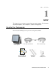
C H A P T E R 1 SETUP This chapter discusses how to set up and test your touchcomputer. For information on peripheral options, refer to Chapter 3, “Options and Upgrades.
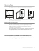
Adjusting the Display The display screen can be adjusted from 0 to 60 degrees, as shown below. CAUTION: To protect the LCD, be sure to hold the base when adjusting the display, and take care to not touch the screen. Setting Up the Operating System The initial setup of the operating system takes approximately 5-10 minutes. Additional time might be needed for different touchcomputer hardware configurations and connected devices.
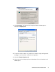
1. Click Customize. The Regional and Language Options window appears. Select the Languages tab. 2. If required, check the boxes for “Install files for complex script and right-to-left languages” and “Install files for East Asian languages.” 3. Select the Regional Options tab. 4. Select your preferred language from the drop-down list in the Standards and formats pane.
5. Click Apply. 6. Select your location from the drop-down list in the Locations pane. 7. Click OK.
Selecting the Time Zone (For Windows XP and POSReady 2009 Only) When the following window appears, you can change the time zone, date, and time of the touchcomputer. After making any changes, click Next to finish. Windows Setup completes the installation of the touchcomputer. Injecting the Languages (For Windows 7 Only) Windows 7 Professional only allows the use of one language at one time. But you can use the Elo TouchSystems language injection tool to update your language preference.
5. Click Inject, and the following window will pop out. 6. Click the drop-down list and select the preference language. 7. Click Inject Selected Language 8. The following window shall be presented.
9. After the language package is installed correctly, press any key to exit this window. 10. Click Exit Exit Restart Selecting the Region (For Windows 7 Only) When the following window appears, you can change the country, time and currency, and keyboard layout of the touchcomputer. After making any changes, click Next to continue.
Choosing the Computer Name (For Windows 7 Only) When the following window appears, you can choose a computer name of the touchcomputer. After making any changes, click Next to continue. Selecting the Update Options (For Windows 7 Only) When the following window appears, you can select one of the update options of the touchcomputer. In general, you can choose Use recommended settings as your default option. After making any changes, click Next to continue.
Reviewing the Time and Date Settings (For Windows 7 Only) When the following window appears, you can set up the time and date of the touchcomputer. After making any changes, click Next to finish. Windows Setup completes the installation of the touchcomputer. Testing Peripherals The touchcomputer can be configured with several different optional peripherals, such as a MSR or cash drawer.
Calibrating the Touchscreen The touchscreen is pre-calibrated for accurate touch response. If for any reason the touchscreen needs to be recalibrated, right-click the Elo icon in the Taskbar and then click “Properties.” The following window opens. NOTE: Calibration is not applicable to APR models. Click the Align button. This launches the calibration program. The window shown below opens. Follow the instructions to calibrate the touchscreen.
Securing the Base There are two mounting options for the D-Series touchcomputer. In both cases, the base must be mounted on a horizontal surface. Option 1: Secure from below. Use the four pretapped holes to secure the touchcomputer from below the mounting surface. The holes are designed to work with ISO metric m6 screws. These screws are not contained in the package, but should be readily available at any hardware store. Option 2: Secure from top. Use the two through holes to secure the base to the surface.
To install these brackets, simply push them onto the sides of the back door of the D-Series touchcomputer, as shown in the figure below. Then insert the advertising material as shown below.
C H A P T E R 2 OPERATION This chapter describes how to control the On-Screen Display (OSD), power buttons, and I/O panel. All adjustments made to the OSD and power controls are automatically saved. User settings remain unchanged after powering off/on or in the case of a power failure. 34 5 6 7 8 9 1 2 1. HDD status LED 2. Computer power LED 3. Head power LED 4. Touch power LED 5. Menu button 6. Left button 7. Right button 8. Select button 9.
On-Screen Display (OSD) OSD Menu 1. To display the OSD Menu, press the Menu button. Press the RIGHT button or LEFT button to toggle and the SELECT button to select from the different OSD sub-menus and functions. 2. When the function you want to change is shown, press the SELECT button. 3. To adjust the value of the function: 4. Pressing the RIGHT button increases the value of the selected OSD control option. 5. Pressing the LEFT button decreases the value of the selected OSD control option.
Feature Description Language Changes language to English, French, Italian, German, Spanish, Japanese, Simplified Chinese, or Traditional Chinese. Recall Sets color recall and recall defaults. Restores original factory settings. Miscellaneous Adjusts sharpness, enables/disables DDCCI function. • Exit Sharpness: Adjusts sharpness of video. Exits the OSD. OSD and Power Button Control The OSD menu and power button are enabled by default. To enable or disable the OSD function: 1.
Head Power Status LED The head power status is indicated by a different LED, which is located at the lower edge of the head (#3 in figure on page 9).
Using the Input/Output Panel To access the input/output (I/O) ports, open the cable cover door on the left side of the unit, as shown below. Optional security screw Opening for cables The touchcomputer provides a number of input and output interfaces for connecting a wide variety of compliant devices as shown in the following figure.
1 8 9 2 3 4 10 11 12 13 5 14 6 7 15 15D1 TOUCHCOMPUTER USER GUIDE 18
Number Port Description 1 Audio Audio in (left), out (center), mic (right) • Audio In • Audio Out: One 3.5mm stereo audio output jack for connecting headphones or external powered speakers • Microphone Input: One 3.5mm microphone input jack for connecting an external microphone 2 Ethernet One RJ45 Ethernet port providing LAN capabilities 3, 8, 9 USB Seven USB 2.
C H A P T E R 3 OPTIONS AND UPGRADES Adding Optional Peripherals When adding a peripheral, complete installation and setup instructions are provided with the field-installable kits.
Magnetic stripe reader (MSR) Barcode scanner Fingerprint reader (FPR) Magnetic Stripe Reader (MSR) You can add a magnetic stripe reader (MSR) to the D-Series touchcomputer using a USB port located on the display head. The MSR is a USB 2.0 device that reads all three data stripes on standard credit cards or driver’s licenses conforming to ISO/ANSI standards. The MSR has foreign language capability.
• Fully supports USB 2.0 • Part number: E145919 Testing the MSR Testing in USB MSR Keyboard (KB) Emulation Mode 1. Open the Notepad application (click Start > Accessories > Notepad). 2. Slide the card through the MSR and verify that the data is displayed in the application window. Testing in USB MSR Human Interface Device (HID) Mode 1. Double-click the MagSwipe HID Demo icon to start the test application.
2. Slide a card through the MSR and verify that the data is displayed in the application window. 3. If the card ID appears in the Reader Output window, the reader is functioning. Customer Display You can optionally add a customer display to the D-Series touchcomputer. Each display has two lines of 20 characters (2x20 VFD). Software application and drivers can be found at the following location www.elotouch.
Feature Description Display type Vacuum fluorescent display Display color Green Display pattern 5 x 7 dot matrix Brightness 350-600 cd/m Characters available 95 alphanumeric & 32 international characters Dot size (X x Y) 0.86 x 1.2 mm Font size 5.5(W) x 10.5(H) Character number 20 characters by 2 lines, for a 5 x 7 dot matrix font Interface USB Part number E326629 or E632206 2 Fingerprint Reader (FPR) The fingerprint reader is powered by the USB bus.
Testing the FPR 1. Double-click the Fingerprint Reader Test icon to start the test application. 2. Place your finger on the fingerprint reader sensor and verify that the image of your fingerprint is displayed on the application window. Barcode Scanner There are two types of optional USB barcode scanners: 1-D or omni-directional. The barcode scanner is only an option if the speaker bar is present. When a scanner is chosen, a USB-SSI (Simple Serial Interface) converter board is included.
• Visible laser diode operating at 650nm • 100+ scans/sec. • RoHS-compliant • Part number: E946856 Omni-directional scanner specifications: • Ability to generate omni-directional scanning pattern • Maximum performance • 2-D scanning ability (PDF417, MicroPDF) • USB powered • Easy communication between host and scanner • Visible laser diode operating at 650nm • 600+ scans/sec.
2. Now scan the barcode below to change the scanning pattern. Using this scanning pattern allows you to read 2-D barcodes (you can still read 1-D barcodes). Testing the Barcode Scanner 1. Determine which port the barcode scanner is using: a. Click Start > Control Panel b. In the Windows Control Panel screen, double-click the Administrative Tools > double-click the Computer Management application (Only for Windows XP and POSReady 2009.) c.
COM value USB serial port 2. From the 1xDx Test Applications folder on the desktop, double-click the Barcode Scanner Test icon to start the SSIContainer application. Connect button Port field 3. Change the Port field value to match the value you retrieved from the Device Manager. 4. Click Connect. You should see the text “Connected” in the Messages field.
Param Number Permanent Param Change New Value 5. In the box labeled Param Number, enter the value 238. 6. In the box labeled New Value, enter the value 1. 7. Check the box labeled Permanent Param Change. 8. Scan a barcode (sample given below). The scanned data should appear in the “Messages” section of SSIContainer screen. The barcode scanner also has the ability to run in USB-KB emulation mode. To enable this option, please install the required drivers. To find the drivers: 1.
Wireless Card A wireless card can be installed as an option in the D-Series touchcomputer to provide wireless LAN capabilities using a mini-PCI slot. A PCI to mini-PCI converter board is provided in the wireless kit. • Typical specifications for the wireless card are: • Mini-PCI interface • Compliant to Mini-PCI industry-standard sizing • 802.
Solid State Drive A solid state drive can be added to (or used to replace) the original hard disk drive. This addition provides additional performance and more mechanically reliability in harsh environments. Part number: E536242 Third-Party Peripherals The D-Series touchcomputer includes two pre-configured ports for a printer and cash drawer. These peripherals are not available from Elo TouchSystems. Printer Port A 24VDC printer power port to connect a compatible receipt printer is provided.
3. Turn off the test equipment. The screen displays “Display is closed.” 4. Click Send 200ms. The software automatically turns on the cash drawer. For additional information, see “Cash Drawer Port Specifications” on page 36. Additional Hard Drives The D-Series touchcomputer comes with one standard hard disk drive.
C H A P T E R 4 SAFETY AND MAINTENANCE Safety Here is some important information on the proper setup and maintenance of your touchcomputer. To reduce the risk of electric shock, follow all safety notices and never open the touchcomputer case. Turn off the product before cleaning (refer to “Care and Handling” on page 30 for proper cleaning methods). Your touchcomputer is equipped with a 3-wire, grounding power cord. The power cord plug only fits into a grounded outlet.
Care and Handling The following tips help keep your touchcomputer functioning at the optimal level. To avoid risk of electric shock, do not disassemble the power adapter or display unit cabinet. The unit is not user serviceable. Remember to unplug the display unit from the power outlet before cleaning. Do not use alcohol (methyl, ethyl, or isopropyl) or any strong solvent. Do not use thinner or benzene, abrasive cleaners, or compressed air.
WEEE Directive In the European Union, the Waste Electrical and Electronic Equipment (WEEE) directive label shown to the left indicates that this product should not be disposed of with household waste. It should be deposited at an appropriate facility for recovery and recycling. Recovering the Operating System If for any reason the touchcomputer’s operating system and software need to be recovered, there are two ways you can recover your system: i.
5. After finished, click Exit Exit System will restart automatically iii. Use the included image to recover the touchcomputer (For Windows 7 Only.) 1. After the TE logo shows up, press F8 (frequently) to enter Advanced Boot Options. 2. Select Repair your computer 3. Click Next OK (Shall not have password) Elo Touch System Tool 4.
5. Click Recover Start Recovery Process 6. After finished, click Exit Exit Restart NOTE: All data is deleted during the recovery process. The user must back up files when necessary. Elo TouchSystems does not accept liability for lost data or software. NOTE: If using POSReady 2009 or Windows 7 and your hard disk is corrupted, you can request a Recovery DVD from Elo TouchSystems customer service. NOTE: The end user must adhere to Microsoft's Licensing Agreement.
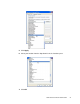
• Instructions to reassign the USB Serial Port 1. For Windows XP or POSReady 2009, right click the “Computer” Click “Properties” “Hardware” “Device Manager”. For Windows 7, right click the “Computer” Click “Properties” “Device Manager”.
2. Double click the “Ports (COM & LPT)” and check all of these “USB Serial Port” settings must be IDENTICAL as the following table.
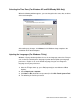
Thus, the settings for these USB Serial Ports should begin at COM3 and end at COM7 in order. 4. To correct it, please follow the instructions below: Double click the port you need to change. In this case, it is COM8. COM8 is the 1st port of these USB serial ports so the “Location:” should be “on USB Serial Converter A”. Please assign this serial port to COM3.
Select “Port Settings” Click “Advanced…” In this case, select COM3 from the drop-down menu click OK OK back to the Device Manager. Follow the same steps to accomplish these settings for other ports.
After finished, right click on “Ports (COM & LPT)” and click Scan for hardware changes. 5. The outcome should be identical as the following diagram.
C H A P T E R 5 TECHNICAL SPECIFICATIONS Touchcomputer Specifications NOTE: Not all operating systems or options are supported in all regions. Please contact your local Elo TouchSystems representative for details. Feature Processor for ESY15D1 Revision A Description Processor for ESY15D1 Revision B and ESY17D1 Processor for ESY15D2 and ESY17D2 Intel Dual-Core Celeron E1500 2.2GHz 512K L2 Cache 800MHz FSB LGA775 Pkg RAM Two slots are available. Qualified vendor is Transcend. Intel Celeron 430 1.
Feature Description Video Intel GMA 3100 (Vista Aero compatible) Operating system Microsoft Windows XP Professional SP3 Microsoft Windows Embedded for Point of Service (WEPOS) Microsoft Windows Vista Business Microsoft Windows POSReady 2009 Microsoft Windows 7 Professional Ports 7 x USB 2.
Feature Description Power supply Internal 12VDC universal-type power supply brick AC input voltage: 100-240V AC Input frequency: 50-60Hz Input current: 2.5-5A Max output power: 270W DC output: +3.3V / 5.0A +5V / 16.0A +12V / 12.0A +24V / 2.3A +5Vsb / 3A -12V / 0.4A Max. power rating for 15” D-Series touchcomputer (without peripherals, receipt printer, cash drawer, or powered serial ports connected: 145W Cash drawer: 2.4W max Receipt printer; 45.
Feature Description Touchcomputer dimensions (max.) for 17” Width: 345 mm Height: 288 mm Depth: 212 mm Dimensions vary with tilt angle and options selected Shipping box dimensions Width: 450mm Height: 475mm Depth: 340mm Weight without peripherals for 15” Actual: 10.03kg (22.1 lbs) Weight without peripherals for 17” Actual: 11.79kg (26 lbs) Display 15” 15.0 in. diagonal Shipping: 12.16kg (26.8 lbs) Shipping: 13.93kg (30.7 lbs) Active matrix TFT LCD 4x3 Display 17” 17.0 in.
Feature Description Peripheral options and upgrades Magnetic stripe reader, 3 tracks Customer display 2 x 20 VFD Biometric fingerprint reader Barcode scanner (1-D or omni/2-D) Second 160GB hard drive Solid State Drive Wireless card Printer power cable 24VDC PoweredUSB Adapter Cable (connect select 24VDC Powered USB devices through the D-Series 24VDC printer power port) Connector Specifications Serial Ports Pin # Standard Ports Signal Name Powered Ports Signal Name 1 SER DCD SER DCD 2 SER RXD SER
Serial Port Power Selection J1/J2 Setting Function All pins open No power Pins 1-2 short/closed 5V (default) Pins 2-3 short/closed 12V Cash Drawer Port Specifications The cash drawer port is 12/24V compatible.
Display Screen Specifications (15”) Feature Specification LCD display 15.0-inch diagonal TFT active matrix LCD Video input signal Analog RGB (0.7Vp-p) Data display channel (DDC) function (plug & play) DDC1, 2B compliant (EDID data only) Display size (useful screen area) 304.128mm (H) x 228.096mm (V) Maximum touchcomputer dimensions 288mm (H) x 345mm (W) x 212mm (D) Pixel pitch 0.297mm (H) x 0.
Feature Specification Horizontal viewing angle (left/right) 70° looking left typical at a CR=10 Contrast ratio 700:1 (typical) Optional touchscreens AccuTouch, IntelliTouch, Acoustic Pulse Recognition 70° looking right typical at a CR=10 Display Screen Specifications (17”) Feature Specification LCD display 17.0-inch diagonal TFT active matrix LCD Video input signal Analog RGB (0.
Feature Specification displays an out of range warning. Brightness (typical) 2 2 2 2 2 2 2 2 No touch 300 cd/m (typical); 250 cd/m (min.) AccuTouch 240 cd/m (typical); 192 cd/m (min.) IntelliTouch APR 270 cd/m (typical); 204 cd/m (min.) 270 cd/m (typical); 204 cd/m (min.) Response time Total: 5ms (Typical) Display color 16.
C H A P T E R 6 TECHNICAL SUPPORT Technical Assistance There are three methods to obtain contact information for technical assistance on the touchcomputer: The touchcomputer The web The phone Using the Touchcomputer You can access support information in System Properties by clicking the Support Information button. You can get to System Properties by either of the following methods: Right-click My Computer and choose Properties.
Using the Phone Call toll-free 1-800-ELO-TOUCH (1-800-356-8682).
REGULATORY INFORMATION I. Electrical Safety Information A) Compliance is required with respect to the voltage, frequency, and current requirements indicated on the manufacturer’s label. Connection to a different power source than those specified herein may result in improper operation, damage to the equipment, invalidation of warranty, or a fire hazard if the requirements are not followed. B) There are no operator-serviceable parts inside this equipment.
C) Notice to Users in the European Union: Use only the provided power cords and interconnecting cabling provided with the equipment.
iv) Plug the digital device into a different AC outlet so the digital device and the receiver are on different branch circuits. v) Disconnect and remove any I/O cables that the digital device does not use. (Unterminated I/O cables are a potential source of high RF emission levels.) vi) Plug the digital device into only a grounded outlet receptacle. Do not use AC adapter plugs. (Removing or cutting the line cord ground may increase RF emission levels and may also present a lethal shock hazard to the user.
WARRANTY Except as otherwise stated herein or in an order acknowledgment delivered to Buyer, Seller warrants to Buyer that the Product shall be free of defects in materials and workmanship. With the exception of the negotiated warranty periods; the warranty for the touchcomputer and components of the product is 3 years. Seller makes no warranty regarding the model life of components. Seller’s suppliers may at any time and from time to time make changes in the components delivered as Products or components.
THESE REMEDIES SHALL BE THE BUYER’S EXCLUSIVE REMEDIES FOR BREACH OF WARRANTY. EXCEPT FOR THE EXPRESS WARRANTY SET FORTH ABOVE, SELLER GRANTS NO OTHER WARRANTIES, EXPRESS OR IMPLIED BY STATUTE OR OTHERWISE, REGARDING THE PRODUCTS, THEIR FITNESS FOR ANY PURPOSE, THEIR QUALITY, THEIR MERCHANTABILITY, THEIR NONINFRINGEMENT, OR OTHERWISE. NO EMPLOYEE OF SELLER OR ANY OTHER PARTY IS AUTHORIZED TO MAKE ANY WARRANTY FOR THE GOODS OTHER THAN THE WARRANTY SET FORTH HEREIN.
INDEX address, Elo TouchSystems, 61 Ethernet port, 19 advertising brackets, 11 fingerprint reader (FPR) overview, 24 specifications, 24 testing, 25 audio ports, description, 19 barcode scanner enabling 2-D scanning, 26 overview, 25 specifications, 25 testing, 27 hard drives adding additional, 32 LED activity, 16 base power status, 15 head power status, 16 base, securing, 11 input/output (I/O) panel accessing, 17 illustration, 17 box contents, 1 brackets, advertising, 11 cables included, 1 printer
operation, 13 options, adding, 20 parallel ports, 19 peripherals adding, 20 third-party, 31 phone number, Elo TouchSystems, 53, 61 ports accessing, 17 audio, 19 cash drawer, 19 compact flash, 19 customer display, 19 Ethernet, 19 illustration, 17 parallel, 19 printer power, 19 PS/2 universal, 19 serial, 19 speaker, 19 USB, 19 VGA, 19 power base, 15 enabling or disabling button lock, 15 printer power port about, 31 cables, 31 description, 19 specifications, 47 language selection, 2, 5 mounting options, 11 op
testing, 30 www.elotouch.com Get the latest... • Product information • Specifications • News on upcoming events • Press release • Software drivers • Touch Monitor Newsletter Getting in Touch with Elo To find out more about Elo’s extensive range of touch solutions, visit our Website at www.elotouch.