:1 3 2 T 4 -0 0 S U Z 6 1:1 03 3 USER GUIDE 1 0 2 Elo Touch Solutions M D A S Interactive Digital Signage Computer Module M For D 2 IDS 3201L/4201L/7001L 3 3 52 SW602000 Rev A
Copyright © 2013 Elo Touch Solutions, Inc. All Rights Reserved. No part of this publication may be reproduced, transmitted, transcribed, stored in a retrieval system, or translated into any language or computer language, in any form or by any means, including, but not limited to, electronic, magnetic, optical, chemical, manual, or otherwise without prior written permission of Elo Touch Solutions, Inc. Disclaimer Z 6 1:1 The information in this document is subject to change without notice.
Table of Contents Chapter 1 - Introduction ........................................................................... 4 Chapter 2 – Unpacking.............................................................................. 5 Chapter 3 – Computer Module Installation ........................................ 6 Chapter 4 – Technical Support ............................................................... 11 Chapter 5 – Safety & Maintenance ........................................................
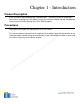
Chapter 1 - Introduction Product Description Interactive Digital Signage Computer Module Gen 2 is designed to slide into the bay on the rear of the Interactive Digital Signage Gen 2 touchmonitors, without any effect on the monitor’s form factor or requiring any extra cabling, turning your Interactive Digital Signage TouchMonitor into an Interactive Digital Signage All-In-One TouchComputer.
Chapter 2 – Unpacking Unpacking the The Digital Signage Computer Module Check that the following items are present and in good condition: • Computer Module • User Guide/ Driver CD • Quick Install Guide • PC Box Cable Cover :1 3 2 T 4 -0 Z 6 1:1 03 3 S M D 2 3 3 2 5 0 S U M D A - 1 0 2 User Guidel–Computer Module SW602000 Rev A, Page 5 of 20
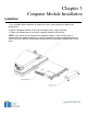
Chapter 3 Computer Module Installation Installation 1. Use a Phillips head screwdriver to remove the access cover plate on the back of the touchmonitor. 2. Slide the Computer Module all the way into the bay until it snaps into place. 3. Tighten the thumbscrews to secure the computer module inside the bay. NOTE: If any cables are connected to the computer module, a cable security cover is included with the computer module kit.
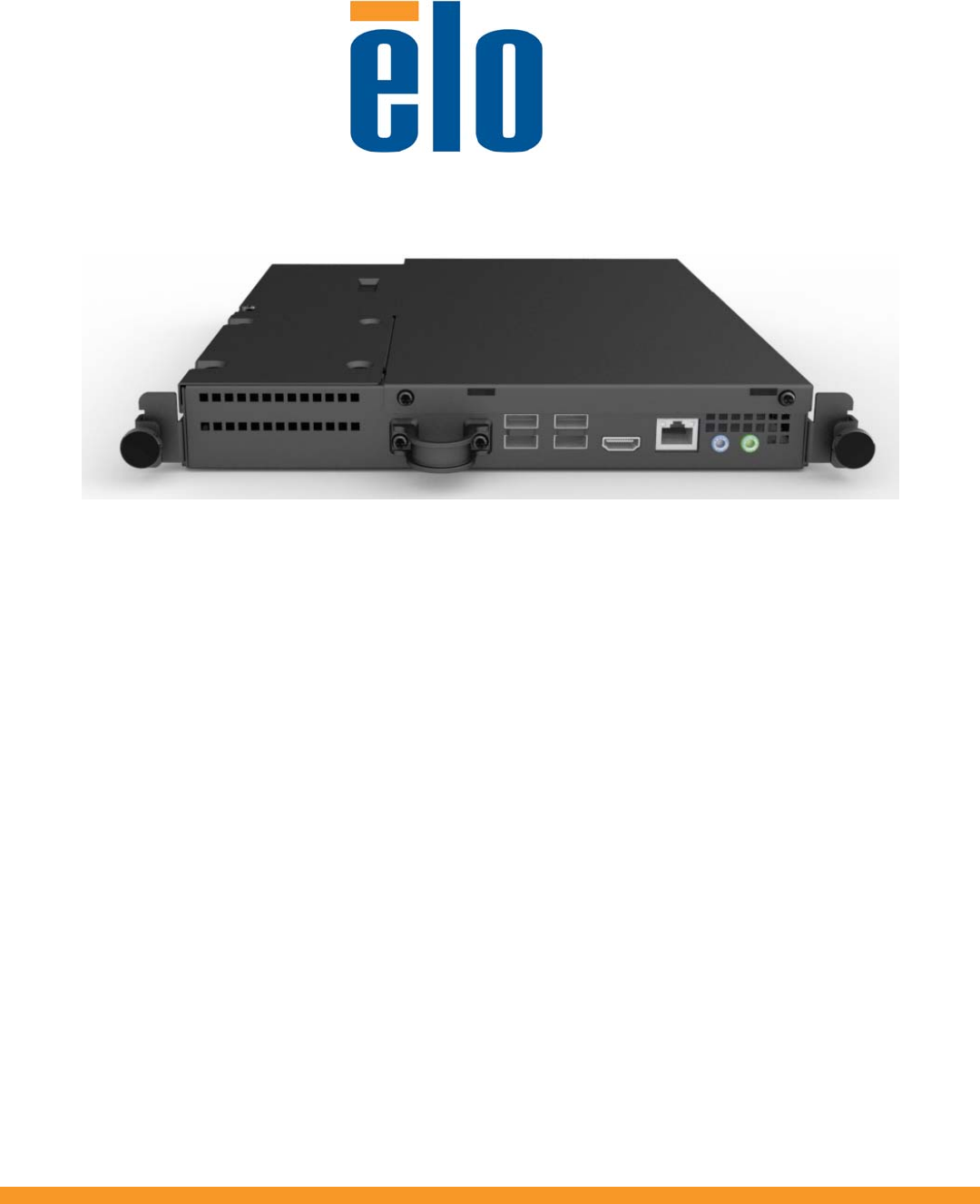
Connector Panel & Interfaces Touchmonitor & Computer Module Connections 1. Once the Computer Module has been installed, connect the AC power cable between the touchmonitor’s POWER IN connector and the AC power source. Z 6 1:1 :1 3 2 T 2. Make any desired connections to the Computer Module 04connector panel. 03to turn on the Computer Module. 3.
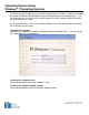
Operating System Setup Windows® 7 Operating Systems The initial setup of the operating system takes approximately 5 minutes. Additional time might be needed for different touchcomputer hardware and operating system configurations. You will need to plug in an external mouse and/or keyboard into the Computer Module connector panel to execute these steps. To set up the Windows 7 OS for the Computer Module, turn on the touchcomputer and follow the instructions on the screen.
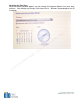
Selecting the Time Zone When the following window appears, you can change the Computer Module’s time zone, date, and time. After making any changes, click Next to finish. Windows Setup completes the OS installation.
Installing the Touchscreen Technology Software Drivers for Elo Computer Modules with Windows 7 Visit the Elo Touch Solutions website www.elotouch.com for: • The latest touch driver versions • Additional touch driver information • Detailed touch driver installation guides • Touch drivers for other operating systems The Computer Module has the Elo Touch Driver already installed on the computer.
Chapter 4 – Technical Support If you are experiencing trouble with your touchmonitor, refer to the following suggestions. If the problem persists, please contact your local dealer or contact Elo Touch Solutions Customer Service. Solutions to Common Problems Problem The Computer Module does not respond when turning on the system. Monitor display is dim Monitor display is blank.
Chapter 5 Safety & Maintenance Safety To avoid risk of electric shock, follow all safety notices and do not disassemble the touchmonitor or Computer Module. They are not user-serviceable. The slots located on the sides and top of the touchmonitor case are for ventilation. Do not block or insert anything inside the ventilation slots. Ensure that your installation is equipped to maintain the specified environmental conditions listed in the unit’s specifications on the Elo Touch Solutions website www.elotouch.
Operating System Recovery - Windows 7 If for any reason the computer module operating system and software need to be recovered TO FACTORY SETTINGS, using Elo recovery utility you can recover your system: 1. When you turn on the computer module after the Elo logo shows up, press F8 repeatedly to enter Advanced Boot Options. 2. Select Repair your computer 3.
Z 6 1:1 6. Once completed, click Exit Recovery Process Æ Exit. The system will restart automatically. :1 3 2 T Injecting the Languages (For Windows-074Only) 3 0 Windows 7 Professional only allows the use of 3 one language at one time. But you can use the 1 Elo Touch Solutions language injection tool0 to update your language preference. English is set 2 as the default language, but you can change - this language to suit your preferences. Mup, press F8 several times to enter Advanced Boot Options. 1.
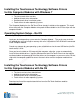
:1 3 2 T 4 -0 5. Click Inject, and the following window will pop out. Z 6 1:1 03 3 S M D 2 3 3 2 5 0 S U M D A - 1 0 2 6. Click the drop-down list and select the preference language. 7. Click Inject Selected Language 8.
Z 6 1:1 9. After the language package is installed correctly, press any key to exit this window. 10.
Chapter 6 - Regulatory Information I. Electrical Safety Information: Compliance is required with respect to the voltage, frequency, and current requirements indicated on the manufacturer’s label. Connection to a different power source than those specified herein will likely result in improper operation, damage to the equipment or pose a fire hazard if the limitations are not followed. There are no operator serviceable parts inside this equipment.
iii) Reorient the affected receiver’s antenna. iv)Plug the digital device into a different AC outlet so the digital device and the receiver are on different branch circuits. v) Disconnect and remove any I/O cables that the digital device does not use.(Unterminated I/O cables are a potential source of high RF emission levels.) vi)Plug the digital device into only a grounded outlet receptacle. Do not use AC adapter plugs.
Chapter 7 – Warranty Information Except as otherwise stated herein, or in an order acknowledgment delivered to Buyer, Seller warrants to Buyer that the Product shall be free of defects in materials and workmanship. The warranty for the touchmonitors, Computer Module, and their components is 3 (three) years. Seller makes no warranty regarding the model life of components. Sellers suppliers may at any time and from time to time make changes in the components delivered as Products or components.
Check out Elo’s Website! www.elotouch.com Get the latest... • Product Information • Specifications • News on upcoming events • Press releases • Software drivers • TouchMonitor Newsletter :1 3 2 T 4 -0 Z 6 1:1 03 3 Getting in Touch with Elo - 1 0 2 To find out more about Elo’s extensive range of touch solutions, visit our website at www.elotouch.