C-Series Touchcomputer for Healthcare Applications User Guide C-Series LCD Multi-function Touchcomputer [19” model shown]
TE Touch Solutions C-Series Touchcomputer for Healthcare Applications User Guide Multi-function Touchcomputer Revision A SW601689 1-800-ELOTOUCH (1-800-356-8682) www.elotouch.
Copyright © 2011 Tyco Electronics Corporation, a TE Connectivity Ltd. Company. All Rights Reserved. No part of this publication may be reproduced, transmitted, transcribed, stored in a retrieval system, or translated into any language or computer language, in any form or by any means, including, but not limited to, electronic, magnetic, optical, chemical, manual, or otherwise without prior written permission of Tyco Electronics Corporation.
Warnings and Cautions Warning • Danger - Explosion hazard. Do not use in the presence of flammable anesthetics, and other flammable materials. • To prevent fire or shock hazards, do not immerse the unit in water or expose it to rain or moisture. • Do not use the unit with an extension cord receptacle or other outlets unless the prongs of the power cord can be fully inserted. • RISK OF ELECTRICAL SHOCK - DO NOT OPEN.
Caution Power cord is used as a disconnection device. To de-energize equipment, disconnect the power cord. This unit must follow the national requirement and local state laws to dispose unit. Before connecting the cables to your Elo touchcomputer, make sure all components are powered OFF. Only approved components complying with IEC60601-1 series can be connected to 19CX/22CX Touchcomputer for Healthcare Applications in Patient Environment.
Medical and Healthcare Application Disclaimer: It is the sole responsibility of any person intending to commercialize, market or use any of TE Connectivity Ltd.
Classification With respect to electrical shock, fire in accordance with UL60601-1 and CAN/CSA C22.2 No. 601.1 This touchcomputer is a Class I (GROUNDED) DEVICE. These touchcomputers are classified NO APPLIED PARTS EQUIPMENT. Protection against harmful ingress of water: INGRESS PROTECTION (IPX1) This touchcomputer shall be classified as ORDINARY EQUIPMENT, not intended or evaluated for use in the presence of flammable anesthetic mixture with air, oxygen, or nitrous oxide.
European Standards and Classifications Standards: EN 60601-1-2: 2007 The EMC limits and test methods are referred to the following standards: Emission: Immunity CISPR11:2003+A1:2004 IEC61000-4-2:2008 ED.2.0 +A2: 2006 (Group I, Class A) IEC61000-4-3:2006+A1:2007ED.3.0 CISPR 22: 2005+A1: 2005, Class A IEC 61000-4-4: 2004+A1:2010 ED.2.0 AS/NZS CISPR 22: 2006, Class A IEC 61000-4-5: 2005 ED.2.0 IEC 61000-3-2: 2005 +A1: 2008+A2: 2009, Class D IEC 61000-3-3: 2008 IEC 610004-6: 2008 ED.3.
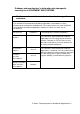
Guidance and manufacturer’s declaration-electromagnetic immunity for all EQUIPMENT AND SYSTEMS Guidance and manufacturer’s declaration-electromagnetic emissions The 19CX/22CX Touchcomputer for Healthcare Applications is intended for use in the electromagnetic environment specified below. The customer or the user of the 19CX/22CX Touchcomputer for Healthcare Applications should assure that it is used in such an environment.
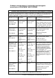
Guidance and manufacturer’s declaration-electromagnetic immunity for all EQUIPMENT AND SYSTEMS Guidance and manufacturer’s declaration-electromagnetic immunity The 19CX/22CX Touchcomputer for Healthcare Applications is intended for use in the electromagnetic environment specified below. The customer, or the user of the 19CX/22CX Touchcomputer for Healthcare Applications, should assure that it is used in such an environment.
Guidance and manufacturer’s declaration-electromagnetic immunity for all EQUIPMENT AND SYSTEMS that are not LIFE-SUPPORTING Guidance and manufacturer’s declaration-electromagnetic immunity The 19CX/22CX Touchcomputer for Healthcare Applications is intended for use in the electromagnetic environment specified below.
3. Field strengths from fixed transmitters, such as base stations for radio (cellular/cordless) telephones and land mobile radios, amateur radio, AM and FM radio broadcast and TV broadcast cannot be predicted theoretically with accuracy. To assess the electromagnetic environment due to fixed RF transmitters, an electromagnetic site survey should be considered.
Recommended separation distances between portable and mobile RF communications equipment and the 19CX/22CX Touchcomputer for Healthcare Applications for all EQUIPTMENT AND SYSTEMS that are not LIFE-SUPPORTING The 19CX/22CX Touchcomputer for Healthcare Applications is intended for use in an electromagnetic environment in which radiated RF disturbances are controlled.
Table of Contents Chapter 1: Setup...................................................................................... 1 Unpacking Your Touchcomputer .................................................................................................. 1 Adjusting the Display .................................................................................................................... 2 Setting Up the Operating System ......................................................................................
Regulatory Information............................................................................38 Warranty ...................................................................................................41 Index..........................................................................................................
C H A P T E R 1 SETUP This chapter discusses how to set up and test your touchcomputer. For information on peripheral options, refer to Chapter 3, “Options and Upgrades.
Adjusting the Display The display screen can be adjusted from 0 to 70 degrees, as shown below. CAUTION: To prevent tipping or dropping, be sure to hold the base when adjusting the display. Setting Up the Operating System If configured with an operating system, the initial setup of the operating system takes approximately 5-10 minutes. Additional time may be needed depending on touchcomputer hardware configurations and connected devices.
Injecting the Languages (For Windows 7 OS OS Only) Windows 7 OS OS Professional only allows the use of one language at one time. But you can use the Elo TouchSystems language injection tool to update your language preference. English is set as the default language, but you can change this language to suit your preferences. 1. After the TE logo shows up, press F8 (frequently) to enter Advanced Boot Options. 2. Select Repair your computer. 3.
6. Click the drop-down list and select the preference language. 7. Click Inject Selected Language 8. The following window shall be presented. 9. After the language package is installed correctly, press any key to exit this window. 10.
Selecting the Region (For Windows 7 OS OS Only) When the following window appears, you can change the country, time and currency, and keyboard layout of the touchcomputer. After making any changes, click Next to continue. Choosing the Computer Name (For Windows 7 OS OS Only) When the following window appears, you can choose a computer name of the touchcomputer.
After making any changes, click Next to continue. Selecting the Update Options (For Windows 7 OS OS Only) When the following window appears, you can select one of the update options of the touchcomputer. In general, you can choose Use recommended settings as your default option. After making any changes, click Next to continue.
Reviewing the Time and Date Settings (For Windows 7 OS Only) When the following window appears, you can set up the time and date of the touchcomputer. After making any changes, click Next to finish. Windows Setup completes the installation of the touchcomputer. Calibrating the Touchscreen The touchscreen is pre-calibrated for accurate touch response. If for any reason the touchscreen needs to be recalibrated, right-click the Elo icon in the Taskbar and then click “Properties.” The following window opens.
Click the Align button. This launches the calibration program. The window shown below opens. Follow the instructions to calibrate the touchscreen.
Securing the Base Use the four pretapped holes to secure the touchcomputer from below the mounting surface. The holes are designed to work with ISO metric M4 screws. Mounting screws are not included with the product but should be readily available at any hardware store. Refer to the figure below for the location of the holes. All dimensions are in millimeters.
C H A P T E R 2 OPERATION This chapter describes how to control the On-Screen Display (OSD), power buttons, and I/O panel. All adjustments made to the OSD and power controls are automatically saved. User settings remain unchanged after powering off/on or in the case of a power failure.
On-Screen Display (OSD) OSD Menu 1. To display the OSD Menu, press the Menu button. Press the RIGHT button or LEFT button to toggle and the SELECT button to select from the different OSD sub-menus and functions. 2. When the function you want to change is shown, press the SELECT button. 3. To adjust the value of the function: 4. Pressing the RIGHT button increases the value of the selected OSD control option. 5. Pressing the LEFT button decreases the value of the selected OSD control option.
Feature Description Brightness Adjust brightness and contrast. Image setting Brightness: Adjusts the backlight of the monitor. Contrast: Adjusts the maximum luminance level of the monitor. Adjusts H position, V position, clock, and phase. H position: Moves the screen horizontally right and left (1 pixel pitch increment). V position: Moves the screen vertically up and down (1 line increment). Clock: Adjusts the ratio of dividing frequency of the dot clock.
To enable or disable the power button (PWR) lock function: 8. Simultaneously press Menu/Exit and the Right (->) key for two seconds. A window appears displaying PWR ENABLE or PWR DISABLE. 9. When the power button lock feature is activated, the power button is disabled. L.E.D. Functionality The C-Series base has a LED indicating the state of the touchcomputer. The table below shows LED state and corresponding color.
Using the Input/Output Panel To access the input/output (I/O) ports, remove the cable cover at the bottom of the unit. A security screw is included and may be used to secure the cable cover to the touchcomputer. Below are the I/O descriptions by model: C3 models C2 models Note: The DB9 Serial (COM) ports are defaulted (from left to right) COM3 and COM4 Note: As a safety precaution, always leave the cable cover door attached when the system is powered on.
C H A P T E R 3 OPTIONS AND UPGRADES Adding Optional Peripherals When adding a peripheral, complete installation and setup instructions are provided with the field-installable kits.
Note: May install up to two (2) Elo Expansion Cards OR one (1) Elo Expansion Card + one (1) PCI-E Expansion Card Note: Peripheral Kits may not meet Electrostatic Discharge (ESD) IEC 61000-4-2 for medical purposes (please consult specifications for each peripheral kit). All peripheral kits DO meet standard ITE ESD requirements. Note: Peripherals may be available only in dark grey. Peripherals may be excluded from healthcare system certifications.
Testing the MSR Testing in USB MSR Keyboard (KB) Emulation Mode 10. Open the Notepad application (click Start > Accessories > Notepad). 11. Slide the card through the MSR and verify that the data is displayed in the application window. Testing in USB MSR Human Interface Device (HID) Mode 12. Double-click the MagSwipe HID Demo icon to start the test application.
13. Slide a card through the MSR and verify that the data is displayed in the application window. 14. If the card ID appears in the Reader Output window, the reader is functioning. Customer Display You can optionally add a customer display to the C-Series touchcomputer to any of the four mounting locations located on the display head top, bottom, left, and right of the touchcomputer. Software application and drivers can be found on www.elotouch.
Fingerprint Reader (FPR) You can add a fingerprint reader to the C-Series touchcomputer to any of the four mounting locations located on the display head top, bottom, left, and right. Software application and drivers can be found in the following directory or on www.elotouch.com C:\EloTouchSystems\SetupFiles\Peripherals The fingerprint reader is powered by the USB bus. The reader optically scans the fingerprint when the user touches the glowing window.
16. Place your finger on the fingerprint reader sensor and verify that the image ofyour fingerprint is displayed on the application window. Cash Drawer Port Card A Cash Drawer Port Card can be installed in any available expansion slot. This card provides: 2 x 12V Powered USB ports 1 x 12V or 24V selectable cash drawer RJ11 port. The voltage setting can be set via jumper on the card prior to installing into the touchcomputer. Test applications can be found in the following directory or on www.
Second VGA Port Card A second VGA video card can be added to any available expansion slot. This card provides a VGA port to drive another VGA display. Software application and drivers can be found in the following directory or on www.elotouch.com C:\EloTouchSystems\SetupFiles\Peripherals Part number: E017487 Wireless Card A wireless adapter can be installed as an option in the C-Series touchcomputer in the I/O area under the cable cover.
Second Hard Disk Drive A second hard disk drive can be added via the second hard drive mounting kit. This addition provides extra data storage or can be used in conjunction with the RAID controller card for RAID functionality. This option occupies a single expansion slot. Part number: E596876 Solid State Drive A solid state drive can be added to (or used to replace) the original hard disk drive. This addition provides additional performance and is more mechanically reliability in harsh environments.
Note: To use this option ALSO requires the purchase and installation of the Elo PCI-E Expansion Card Option Kit, part number E827958. Parallel Port Card A parallel port card can be added to any Expansion slot. This option provides a parallel port for printer interfaces only. Software drivers can be found in the following directory or on www.elotouch.
Feature Description 2.0MP Webcam w/2 x Digital Microphone 2 Million Pixel Webcam Module USB Type Video Resolution 1.0, 1.1 or 2.0 1600x1200, 1280x1024, 640x480, 352x388, 320x240, 176x144, 160x120 Auto Frame Rate 5fps max @ 2.
C H A P T E R 4 SAFETY AND MAINTENANCE Safety Important information regarding the proper setup and maintenance of your touchcomputer: To reduce the risk of electric shock, follow all safety notices and never open the touchcomputer case. Turn off the product before cleaning (refer to “Care and Handling” on page 26 for proper cleaning methods). Your touchcomputer is equipped with a 3-wire, grounding power cord. The power cord plug only fits into a grounded outlet.
Care and Handling The following tips help keep your touchcomputer functioning at the optimal level. Power down the unit and disconnect from the electrical mains prior to engaging in any cleaning activities. Take care to ensure no leakage of solution into the system. IF ANY FLUID INGRESS INTO THE UNIT DURING CLEANING IS SUSPECTED, DO NOT POWER ON THE UNIT. Call the manufacturer at the contact numbers listed below to have your unit inspected by a qualified technician prior to powering on.
Warning This product consists of devices that might contain mercury, which must be recycled or disposed of in accordance with local, state, or federal laws. (Within this system, the backlight lamps in the touchcomputer display contain mercury.) WEEE Directive In the European Union, the Waste Electrical and Electronic Equipment (WEEE) directive label shown to the left indicates that this product should not be disposed of with household waste.
5. Click Recover Start Recovery Process 6. After finished, click Exit Exit Restart ii. Use the recovery DVD to recover the touchcomputer. Recovery DVD’s can be ordered if necessary from TE Touch Solutions customer service. 1. Connect the USB DVD drive to the touchcomputer. 2. Place the recovery DVD in the DVD drive.
3. Press “F11” to enter Device Boot Menu and boot touchcomputer from DVD. 4. After entering the Elo Touch System Tool, click “WINPE” button. 5. Once you see the “Command Prompt” window, type “win7” to start recovery process for Windows 7 OS. 6. Follow the on-screen instruction to complete recovery. NOTE: All data is deleted during the recovery process. The user must back up files when necessary. TE Touch Solutions does not accept liability for lost data or software.
NOTE: If using Windows 7 OS and your hard disk is corrupts, you can request a Recovery DVD from TE Touch Solutions customer service. NOTE: The end user must adhere to Microsoft's Licensing Agreement. NOTE: After you recovered your touchcomputer by using the included image, the operating system might reassign your USB Serial Ports during the first bootup. You can follow the instructions below to reassign it manually. Instructions to reassign the USB Serial Port 1.
2. Double click the “Ports (COM & LPT)” and check all of these “USB Serial Port” settings must be IDENTICAL as the following table. Description USB Serial Port (COM3) USB Serial Port (COM4) Location On USB Serial Converter A On USB Serial Converter B 3. If you see a situation as below, it shows the operating system has reassigned these serial ports. You need to correct it manually.
In usual, even if the operating system reassigns these serial ports, they are still in order. In this case, you should change it as the following table. Original one USB Serial Port (COM5) USB Serial Port (COM6) Change to USB Serial Port (COM3) USB Serial Port (COM4) Thus, the settings for these USB Serial Ports should begin at COM3 and end at COM4 in order. 4. To correct it, please follow the instructions below: Double click the port you need to change. In this case, it is COM5.
COM5 is the 1st port of these USB serial ports so the “Location:” should be “on USB Serial Converter A”. Please assign this serial port to COM3. (COM4 for the USB Serial Converter B).
Change to COM3 Location Information Select “Port Settings” Click “Advanced…” C-Series Touchcomputer for Healthcare Applications User Guide 34
In this case, select COM3 from the drop‐down menu click OK OK back to the Device Manager. Follow the same steps to accomplish these settings for other ports. After finished, right click on “Ports (COM & LPT)” and click Scan for hardware changes. 5. The outcome should be identical as the following diagram.
COM3 location: USB Serial Converter A COM4 location: USB Serial Converter B C-Series Touchcomputer for Healthcare Applications User Guide 36
C H A P T E R 5 TECHNICAL SUPPORT Technical Assistance There are three methods to obtain contact information for technical assistance on the touchcomputer: The web The phone Using the Web For technical support, go to www.elotouch.com/go/contactsupport. For current Elo news, product updates, and announcements, or to register to receive our Touchcomputer newsletter, go to www.elotouch.com/go/news.
REGULATORY INFORMATION I. Electrical Safety Information A) Compliance is required with respect to the voltage, frequency, and current requirements indicated on the manufacturer’s label. Connection to a different power source than those specified herein may result in improper operation, damage to the equipment, invalidation of warranty, or a fire hazard if the requirements are not followed. B) There are no operator-serviceable parts inside this equipment.
B) Notice to Users in Canada: This equipment complies with the Class A limits for radio noise emissions from digital apparatus as established by the Radio Interference Regulations of Industry Canada. C) Notice to Users in the European Union: Use only the provided power cords and interconnecting cabling provided with the equipment. Substitution of provided cords and cabling may compromise electrical safety or CE Mark Certification for emissions or immunity as required by the standards listed below.
b) If you determine that this equipment is causing the interference, try to correct the interference by using one or more of the following measures: i) Move the digital device away from the affected receiver. ii) Reposition (turn) the digital device with respect to the affected receiver. iii) Reorient the affected receiver’s antenna. iv) Plug the digital device into a different AC outlet so the digital device and the receiver are on different branch circuits.
WARRANTY Except as otherwise stated herein or in an order acknowledgment delivered to Buyer, Seller warrants to Buyer that the Product shall be free of defects in materials and workmanship. With the exception of the negotiated warranty periods; the warranty for the touchcomputer and components of the product is 3 years. Seller makes no warranty regarding the model life of components. Seller’s suppliers may at any time and from time to time make changes in the components delivered as Products or components.
THESE REMEDIES SHALL BE THE BUYER’S EXCLUSIVE REMEDIES FOR BREACH OF WARRANTY. EXCEPT FOR THE EXPRESS WARRANTY SET FORTH ABOVE, SELLER GRANTS NO OTHER WARRANTIES, EXPRESS OR IMPLIED BY STATUTE OR OTHERWISE, REGARDING THE PRODUCTS, THEIR FITNESS FOR ANY PURPOSE, THEIR QUALITY, THEIR MERCHANTABILITY, THEIR NONINFRINGEMENT, OR OTHERWISE. NO EMPLOYEE OF SELLER OR ANY OTHER PARTY IS AUTHORIZED TO MAKE ANY WARRANTY FOR THE GOODS OTHER THAN THE WARRANTY SET FORTH HEREIN.
INDEX address, TE Touch Solutions, 45 base power status, 13 base, securing, 9 box contents, 1 cables included, 1 calibration, 7 certifications, 40 contact information, 37 controls, location diagram, 10 customer display overview, 18 specifications, 18 on-screen display (OSD) enabling or disabling menu, 12 menu settings, 11 operating system recovering, 27 setting up, 2 operation, 10 options, adding, 15 peripherals adding, 15 phone number, TE Touch Solutions, 37, 45 ports accessing, 14 customer support, 37 d
care and handling, 26 upgrades, adding, 15 warranty, 41 website, TE Touch Solutions, 37, 45 WEEE directive, 27 wireless card overview, 21 specifications, 21 testing, 21 www.elotouch.com Get the latest...
To find out more about the extensive range of Elo touch solutions, vist www.elotouch.com or simply call the office nearest you: Europe Asia-Pacific Tyco Electronics Corporation (TE Touch Solutions Division) Tyco Electronics Raychem B.V.B.A. Sun Hamada Bldg.