Touchmonitor User Guide 1519LM 15.6” LCD Desktop Touchmonitor 1919LM 18.
Elo TouchSystems 15.6” and 18.5” LCD Touchmonitor User Guide Revision A SW601463 Elo TouchSystems 1-800-ELOTOUCH www.elotouch.
Copyright © 2010 Tyco Electronics. All Rights Reserved. No part of this publication may be reproduced, transmitted, transcribed, stored in a retrieval system, or translated into any language or computer language, in any form or by any means, including, but not limited to, electronic, magnetic, optical, chemical, manual, or otherwise without prior written permission of Tyco Electronics. Disclaimer The information in this document is subject to change without notice.
Warnings and Cautions ! Warning • Danger - Explosion hazard. Do not use in the presence of flammable anesthetics, and other flammable materials. • To prevent fire or shock hazards, do not immerse the unit in water or expose it to rain or moisture. • Do not use the unit with an extension cord receptacle or other outlets unless the prongs of the power cord can be fully inserted. • RISK OF ELECTRICAL SHOCK - DO NOT OPEN.
Caution • Power cord is used as a disconnection device. To de-energize equipment, disconnect the power cord. • This unit must follow the national requirement and local state laws to dispose unit. • Before connecting the cables to your Elo touchmonitor, make sure all components are powered OFF. Only approved components complying with IEC60601-1 series can be connected to ET1519/ 1919LM in Patient Environment.
Medical and Healthcare Application Disclaimer: If the Purchaser intends to commercialize, market or use any product for medical or healthcare applications, it is the sole responsibility of the Purchaser to ensure that the product is adequate and appropriate for the Purchaser’s intended use and complies with all applicable laws, regulations, codes and standards including but not limited to the European Union Medical Device Directive, United States Federal Food, Drug, and Cosmetic Act, regulations of the Unit
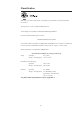
Classification E342290 With respect to electrical shock, fire in accordance with UL60601-1 and CAN/CSA C22.2 No. 60601-1 This monitor is a Class I (GROUNDED) DEVICE. These displays are classified NO APPLIED PARTS EQUIPMENT. Protection against harmful ingress of water: INGRESS PROTECTION (IPX0) This monitor shall be classified as ORDINARY EQUIPMENT, not intended or evaluated for use in the presence of flammable anesthetic mixture with air, oxygen, or nitrous oxide. Mode of Operation: CONTINUOUS OPERATION.
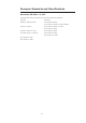
European Standards and Classifications Standards: EN 60601-1-2: 2007 The EMC limits and test methods are referred to the following standards: Emission: Immunity CISPR 11: 2009+A1:2010 IEC 61000-4-2: 2008 IEC 61000-4-3: 2006+A1:2007+A2:2010 (Group 1, Class B) IEC 61000-4-4: 2004 + A1:2010 IEC 61000-4-5: 2005 EN55011: 1998+A1: 1999+ IEC 61000-4-6: 2008 A2: 2002, (Group 1, Class B) IEC 61000-4-8: 2009 IEC 61000-4-11: 2004 IEC 61000-3-2: 2005 IEC 61000-3-3; 2008 viii
Guidance and manufacturer’s declaration-electromagnetic immunityfor all EQUIPMENT AND SYSTEMS Guidance and manufacturer’s declaration-electromagnetic emissions The ET1519/1919LM is intended for use in the electromagnetic environment specified below. The customer or the user of the ET1519/1919LM should assure that it is used in such an environment.
Guidance and manufacturer’s declaration-electromagnetic immunityfor all EQUIPMENT AND SYSTEMS Guidance and manufacturer’s declaration-electromagnetic immunity The ET1519/1919LM is intended for use in the electromagnetic environment specified below. The customer or the user of the ET1519/1919LM should assure that it is used in such an environment.
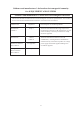
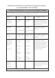
Guidance and manufacturer’s declaration-electromagnetic immunityfor all EQUIPMENT AND SYSTEMS that are not LIFE-SUPPORTING Guidance and manufacturer’s declaration-electromagnetic immunity The ET1519/1919LM is intended for use in the electromagnetic environment specified below. The user of the ET1519/1919LM should assure that it is used in such an environment. Immunity test IEC 60601 test level Compliance level Electromagnetic environment-guidelines Conducted RF d=1.
Recommended separation distance between portable and mobile RF communications equipment and the ET1519/1919LM for all EQUIPMENT AND SYSTEMS that are not LIFE-SUPPORTING Recommended separation distances between portable and mobile RF communications equipment and the ET1519/1919LM The ET1519/1919LM is intended for use in an electromagnetic environment in which radiated RF disturbances are controlled.
Table of Contents Chapter 1 Introduction 1 Appendix B Product Description........................................................................ 1 Precautions......................................................................................... 1 Care and Handling of Your Touchmonitor............................... 21 Chapter 2 Installation and Setup Touchmonitor Safety....................................................................... 20 Appendix C Touchmonitor Specifications..............
CHAPTER 1 INTRODUCTION Product Description Your new 1519/1919LM touchmonitor combines the reliable performance of touch technology with the latest advances in LCD display design. This combination of features creates a natural flow of information between a user and your touchmonitor. This LCD monitor incorporates a 15.6” or 18.5” color active matrix thin-film-transistor (TFT) liquid crystal display to provide high quality display performance.
CHAPTER 2 INSTALLATION AND SETUP This chapter discusses how to install the 1519/1919LM LCD touchmonitor and the driver software.
Power cable for North America models USA/UL Power cable Power cable for European models Europe/VDE power cable UK power cable Power cable for Japan models Japanese/PSE power cable Adapter/Terminal 2-3
Assembling the stand plate Pushing the stand plate toward the stand untill it is tight, then fasten the stand plate using captive screw.
Interface Connection Note: Before connecting the cables to your touchmonitor and PC, be sure that the computer and touchmonitor are turned off. DVI Cable Headphone Cable 1 2 2 3 Serial Cable 3 4 Audio Cable VGA Cable USB Cable Power Brick 1. Connect DC cable of the power brick to the monitor and the other end through AC power cable to the AC outlet. 2.
Product Overview Main Unit Rear View TM Kensington Lock The KensingtonTM lock is a security device that prevents theft. To find out more about this security device, go to http://www.kensington.com.
Installing the Driver Software Elo TouchSystems provides driver software that allows your touchmonitor to work with your computer. Drivers are located on the enclosed CD-ROM for the following operating systems: • Windows 7 • Windows Vista • Windows XP • Windows 2000 • Windows Me • Windows 98 • Windows 95 • Windows NT 4.0 • Windows 3.1 • MS-DOS Additional drivers and driver information for other operating systems are available on the Elo TouchSystems web site at www.elotouch.com.
Installing the Serial Touch Driver (not applicable to Acoustic Pulse Recognition monitor) Installing the Serial Touch Driver for Windows 7, Windows Vista, Windows XP, Windows 2000, ME, 95/98 and NT4.0. NOTE: For Windows 2000 and NT4.0 you must have administrator access rights to install the driver. Make sure the serial connector (RS232) is plugged into the monitor and an open com port on the PC. 1 Insert the Elo CD-ROM in your computer's CD-ROM drive.
Installing the Serial Touch Driver for MS-DOS and Windows 3.1 You must have a DOS mouse driver (MOUSE.COM) installed for your mouse if you wish to continue using your mouse along with your touchmonitor in DOS. To install Windows 3.x and MS-DOS touch driver from Windows 95/98, follow the directions below: 1 Insert the CD-ROM in your computer’s CD-ROM drive. 2 From DOS, type d: and press the Enter key to select the CD-ROM (your CD-ROM drive may be mapped to a different drive letter).
Installing the USB Touch Driver Installing the USB Touch Driver for Windows 7, Windows Vista, Windows XP, Windows 2000, ME and Windows 98. 1 Insert the Elo CD-ROM in your computer’s CD-ROM drive. If Windows 98 or Windows 2000 starts the Add New Hardware Wizard, do the following: 2 Choose Next. Select “Search for the best driver for your device (Recommended)” and choose Next.
CHAPTER 3 OPERATION About Touchmonitor Adjustments Your touchmonitor will not likely require adjustment. However, variations in video output and application may require adjustments to the touchmonitor to optimize the quality of the display. For best performance, the input video resolution should be the touchmonitors native resolution, 1366 x 768. Use the Display control panel in Windows to choose 1366 x 768 resolution. Operating in other resolutions will degrade video performance.
Bottom Panel Controls SELECT MENU Audio Output SELECT 5 4 MENU 3 2 1 Control 1 Menu/Exit Function Display/Exits the OSD menus. 2 1. Enter Luminance of the OSD. 2. Increase value of the adjustment item. 3. Move OSD selection upward. 3 1. Enter Audio of the OSD. 2. Decrease value of the adjustment item. 3. Move OSD selection downward . 4 Select 1. Video source select. Options are: VGA Priority, DVI Priority. Default: DVI Priority 2.
Controls and Adjustment On Screen Display (OSD) Menu Functions To Display and Select the OSD Functions: 1. Press the Menu key to activate the OSD menu. 2. Use or to move upward or downward through the menu. Press the “Select” key, execute the function or enter the sub-menu. 3. To quit the OSD screen at any time during the operation, press the Menu key. If no keys are pressed for a short time period, the OSD automatically disappears.
On Screen Display(OSD) Control Options Control Auto-Adjust Luminance .Brightness .Contrast Image Setting .H-Position .V-Position .Clock .Phase Description Select “Auto-Adjust” to enable this function. The Auto-Adjust will automatically adjust V-Position, H-Position, Clock and Phase. Color Audio .Mute .Volume Press or to select 9300, 6500, 5500, 7500 and USER. Only when selecting USER can you make adjustments to the R/G/B content values.
Preset Modes To reduce the need for adjustment for different modes, the monitor has default setting modes that are most commonly used as given in the table below. If any of these display modes are detected, the monitor automatically adjusts the picture size and centering. When none of the modes are matched, the user can store their preferred modes in the user modes. The monitor is capable of storing up to 7 user modes.
Power Management System Mode On Sleep Off Power Consumption (12VDC input) <42W <4W <2W It is recommended to switch the monitor off when it is not in use for a long period of time. NOTE: Complies to VESA Power Management (DPM) standards. To activate the monitor, press any key on the keyboard or move the mouse or touch the touchscreen. In order for the touchscreen to bring the monitor from the DPM system, the touchscreen function must be fully operational.
CHAPTER 4 TROUBLESHOOTING If you are experiencing trouble with your touchmonitor, refer to the following table. If the problem persists, please contact your local dealer or the Elo service center. Solutions to Common Problems Problem Suggestion(s) The monitor does not respond 1. Check that the monitor’s Power Switch is on. when turning on the system. 2. Turn off the power and check the monitor’s DC power cord and signal cable for proper connection.
APPENDIX A NATIVE RESOLUTION The native resolution of a monitor is the resolution level at which the LCD panel is designed to perform best. For the LCD touchmonitor, the native resolution is 1366 x 768 for the 15.6 inch and 18.5 inch size. In almost all cases, screen images look best when viewed at their native resolution. The resolution setting of a monitor can be lowered but not increased.
As an example, a SVGA resolution LCD panel has 800 pixels horizontally by 600 pixels vertically. Input video is also represented by the same terms. XGA input video has a format of 1024 pixels horizontally by 768 pixels vertically. When the input pixels contained in the video input format match the native resolution of the panel, there is a one to one correspondence of mapping of input video pixels to LCD pixels.
APPENDIX B TOUCHMONITOR SAFETY This manual contains information that is important for the proper setup and maintenance of your touchmonitor. Before setting up and powering on your new touchmonitor, read through this manual, especially Chapter 2 (Installation), and Chapter 3 (Operation). 1 To reduce the risk of electric shock, follow all safety notices and never open the touchmonitor case. 2 Turn off the product before cleaning.
Care and Handling of Your Touchmonitor The following tips will help keep your touchmonitor functioning at the optimal level. • To avoid risk of electric shock, do not disassemble the brick power supply or display unit cabinet. The unit is not user serviceable. Remember to unplug the display unit from the power outlet before cleaning. • Do not use alcohol (methyl, ethyl or isopropyl) or any strong dissolvent. Do not use thinner or benzene, abrasive cleaners or compressed air.
APPENDIX C TECHNICAL SPECIFICATIONS C-22
Touchmonitor Specifications Model LCD Display Display Size Pixel Pitch Native Resolution Display Mode Contrast Ratio Brightness Response Time Display Color Viewing Angle Input Video Signal Type Sync Connector Bottom Controls Speakers Audio Input Connector Headphone Output connector OSD Plug & Play Touch Panel Power Adapter Operating Conditions Temperature Humidity Al
Touchmonitor Specifications Model LCD Display Display Size Pixel Pitch Native Resolution Display Mode Contrast Ratio Brightness Response Time Display Color Viewing Angle Input Video Signal Type Sync Connector Bottom Controls Speakers Audio Input Connector Headphone Output connector OSD Plug & Play Touch Panel Power Adapter Operating Conditions Temperature Humidity Altitu
15” LCD Touchmonitor (1519LM) Dimensions C-25
19” LCD Touchmonitor (1919LM) Dimensions 26
REGULATORY INFORMATION I. Electrical Safety Information: A) B) C) Compliance is required with respect to the voltage, frequency, and current requirements indicated on the manufacturer’s label. Connection to a different power source than those specified herein will likely result in improper operation, damage to the equipment or pose a fire hazard if the limitations are not followed. There are no operator serviceable parts inside this equipment.
D) General Information to all Users: This equipment generates, uses and can radiate radio frequency energy. If not installed and used according to this manual the equipment may cause interference with radio and television communications. There is, however, no guarantee that interference will not occur in any particular installation due to site-specific factors.
III.
WARRANTY Except as otherwise stated herein or in an order acknowledgment delivered to Buyer, Seller warrants to Buyer that the Product shall be free of defects in materials and workmanship. The warranty for the touchmonitors and components of the product is 3 (three) years. Seller makes no warranty regarding the model life of components. Seller’s suppliers may at any time and from time to time make changes in the components delivered as Products or components.
THESE REMEDIES SHALL BE THE BUYER’S EXCLUSIVE REMEDIES FOR BREACH OF WARRANTY. EXCEPT FOR THE EXPRESS WARRANTY SET FORTH ABOVE, SELLER GRANTS NO OTHER WARRANTIES, EXPRESS OR IMPLIED BY STATUTE OR OTHERWISE, REGARDING THE PRODUCTS, THEIR FITNESS FOR ANY PURPOSE, THEIR QUALITY, THEIR MERCHANTABILITY, THEIR NONINFRINGEMENT, OR OTHERWISE. NO EMPLOYEE OF SELLER OR ANY OTHER PARTY IS AUTHORIZED TO MAKE ANY WARRANTY FOR THE GOODS OTHER THAN THE WARRANTY SET FORTH HEREIN.
Check out Elo’s Website! www.elotouch.com Get the latest... • Product information • Specifications • News on upcoming events • Press release • Software drivers • Touchmonitor Newsletter Getting in Touch with Elo To find out more about Elo’s extensive range of touch solutions, visit our Website at www.elotouch.