Composer User Manual for SimplIQ Servo Drives Some changes have been made to the content in this manual and they will be incorporated into the upcoming release. To view the Addendum, click here.
Important Notice This document is delivered subject to the following conditions and restrictions: This manual contains proprietary information belonging to Elmo Motion Control Ltd. Such information is supplied solely for the purpose of assisting users of the Elmo Composer software application, in conjunction with Elmo’s SimplIQ line of digital servo drives. The text and graphics included in this manual are for the purpose of illustration and reference only.
Elmo Composer User Manual MAN-COMPUM (Ver. 1.9) Contents Chapter 1: Introduction............................................................................................................... 1-1 1.1 Composer Description....................................................................................................... 1-1 1.2 System Requirements ........................................................................................................ 1-2 1.3 Composer Installation ........................
Elmo Composer User Manual Contents MAN-COMPUM (Ver. 1.9) 3.2.1 Motion Monitor Recorder ................................................................................. 3-4 3.2.2 Motion Monitor Indicators ............................................................................... 3-7 3.3 The Smart Terminal ........................................................................................................... 3-8 3.3.1 Terminal ......................................................................
Composer User Manual MAN-COMPUM (Ver. 1.9) Chapter 1: Introduction The Composer is a sophisticated suite of Windows-based software designed by Elmo to enable you to quickly and easily set up and fine tune your motion control systems using Elmo’s digital servo drives. The Composer can work with any brush or brushless servo motor.
Composer User Manual Introduction MAN-COMPUM (Ver. 1.9) A networking option, which provides direct communication with multiple servo drives. You may set up as many as eight drives to communicate with the Composer via RS-232 communication, using different COM ports. In addition, you may connect up to 127 drives – each with a unique ID number – through CAN communication; the Composer supports the CANopen protocol for this type of network.
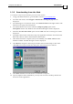
Composer User Manual Introduction MAN-COMPUM (Ver. 1.9) 1.3.2 Downloading from the Web To install the Composer by downloading it from the Elmo website: 1. Using your Internet browser, go to the Elmo website: www.elmomc.com. 2. From the main menu, select Support – Downloads. The Support page will be displayed. 3. From the Support - Downloads menu, select Software Tools in the right column. The Software Tools page will be displayed. 4.
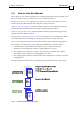
Composer User Manual Introduction MAN-COMPUM (Ver. 1.9) 1.4 How to Use this Manual This Composer user manual explains how to install the application, tune your Elmo servo drive and use the Composer software tools. It is organized as follows: Chapter 2, Using the Wizard, explains how to connect your Elmo servo drive to your PC and the motor, and then tune the drive using the Composer Wizard.
Composer User Manual MAN-COMPUM (Ver. 1.9) Chapter 2: Using the Wizard After connecting your Elmo servo drive to the motor and to the PC, you need to define its setup parameters in order to customize it to the motor, create the application (with the network, drive and motor parameters) and specify the dedicated I/O components.
Composer User Manual Using the Wizard MAN-COMPUM (Ver. 1.9) The motor axes should be free to move plus or minus several electric poles. While the Wizard can operate with noisy or fairly inaccurate encoders, encoder accuracy should be no less than several hundreds per cycle. 2.
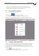
Composer User Manual Using the Wizard MAN-COMPUM (Ver. 1.9) The Application Name and Communication Type dialog box will be displayed, as follows: This dialog box enables you to name your new application and to define the communication type used with it. 1. In the Application Name text box, type a name that clearly defines the new application.
Composer User Manual Using the Wizard MAN-COMPUM (Ver. 1.9) 2.3.1 Defining RS-232 Communication If you selected RS-232 as your communication type, the RS-232 Properties dialog box will be displayed, as follows: Use the Com Port, Bits per Second and Parity drop-down lists to select the appropriate setting for each parameter. You can use the Restore Defaults button to recall the default settings; the defaults are COM 1 (Com Port), 19,200 (Bits Per Second) and None (Parity).
Composer User Manual Using the Wizard MAN-COMPUM (Ver. 1.9) 4. From the Manufacturer drop-down list, select the name of the board manufacturer. 5. From the Board Type drop-down list, select the name of the CAN board installed in your computer. 6. In the CAN Number text box, type the number of the on-board controller (0 or 1) defined in the board setup process. The Segment Address and the IRQ value, defined during CAN installation, are displayed here only for reference. 7.
Composer User Manual Using the Wizard MAN-COMPUM (Ver. 1.9) 1. Check the Elmo servo drive name displayed in the ELMO Driver version text box (read from the controller) and verify that you are working with the correct drive. 2. This dialog lists motor manufacturers and motors that are stored in the drive database. If these lists include your motor, select the appropriate names from the Motor Manufacturer Name and Motor P/N lists.
Composer User Manual Using the Wizard MAN-COMPUM (Ver. 1.9) 4. Click Next to continue defining your motor. The Commutation Feedback Parameters dialog box will be displayed. 5. From the Current Main Commutation Feedback drop-down list, select the primary encoder type used in your motor (the system may also have an auxiliary feedback mechanism).
Composer User Manual Using the Wizard MAN-COMPUM (Ver. 1.
Composer User Manual Using the Wizard MAN-COMPUM (Ver. 1.9) • Absolute Single Turn Position Resolution–a drop down menu that represents, in terms of bits, single-turn feedback cycle. The number of counts would be 2^number of bits. This value is practically the digital absolute resolution derived from the feedback and can be read from the encoder data sheet. Sine/cosine resolution improves this value but is derived from firmware manipulation. The value can be read from the encoder data sheet.
Composer User Manual Using the Wizard MAN-COMPUM (Ver. 1.9) N: Number of sine/cosine signals per mechanical resolution For linear motors: Multiplication Factor ≤ 10 9 * N L where: N: Period of a single analog sine\cosine. Typically in mm/inches L: Length of the linear sensor. Typically in meters/legs Both N and L must be the same (distance) units.
Composer User Manual Using the Wizard MAN-COMPUM (Ver. 1.9) For Heidenhain feedback: • Serial Interface– a drop down menu with a list of the serial interfaces: Hiperface or EnDat2.1 formats. • Magnetic Pitch– an Edit Box which represents the distance of one electrical cycle in millimeters. The value is taken from the motor’s data sheet. • Measurement Length (Hiperface) or Measuring Length (EnDat)– an Edit Box which represents the length of linear sensor in millimeters.
Composer User Manual Using the Wizard MAN-COMPUM (Ver. 1.9) 2.6 Defining System Limits After defining your motor and commutation parameters (clicking Next in the Commutation Feedback Parameters dialog box), the System Definitions and Limits dialog box will be displayed to enable you to define how your system should behave when it reaches an operational limit. You need to specify each value; these parameters are NOT defined automatically by the system.
Composer User Manual Using the Wizard MAN-COMPUM (Ver. 1.9) 1. 2. In the Driver Parameters block, enter the following values: Application Continuous Current: the maximum current, in amperes, to be used with the connected motor. This value must be equal to or less than the Motor Continuous Stall Current (defined in the System Database dialog box, section 2.4) and the value displayed in the Driver Continuous Current text box.
Composer User Manual Using the Wizard MAN-COMPUM (Ver. 1.9) 4. From the Select Function Behaviors and Logic Level list, select the relevant function options and the logic level at which they are activated. The following table explains the options available for each of the switches: Function Behavior Description when Activated Inhibit (Freewheel) The drive shuts down and the motor runs freely. Hard Stop The motor stops under hardware control. Ignore Uncommitted input.
Composer User Manual Using the Wizard MAN-COMPUM (Ver. 1.9) 7. Click Next to continue to the tuning steps. The Custom dialog box will be displayed. If this is a first-time configuration, the Composer Wizard automatically selects the steps that are required for fully tuning the drive and motor that you have defined. If you selected a Rotating Brush motor type in the System Database dialog box (section 2.4), steps 1 and 2 will automatically be deselected.
Composer User Manual Using the Wizard MAN-COMPUM (Ver. 1.9) 2.7 2-16 Tuning the Current Loop The Composer Wizard begins the tuning process with the current loop because the current controller must be properly tuned before any other process can be successfully carried out. When you select Step 1, Tuning Current Loop from the Custom dialog box, a Tuning Current Loop dialog box similar to the following is displayed.
Composer User Manual Using the Wizard MAN-COMPUM (Ver. 1.9) 2.8 Configuring Commutation For all brushless motors, you need to define the parameters for commutation between the servo drive and the motor. This process automatically determines the correct phase sequence needed for optimal commutation. When digital Hall sensors are used, the system also finds the offset from the commutating points.
Composer User Manual Using the Wizard MAN-COMPUM (Ver. 1.9) 3. In order to define the positive and negative directions for the motor, click either Yes to accept the present motor direction as positive or click No to change the present motor direction to negative. The motor will then move back to its starting position (for subsequent tuning) and the system will store the commutation information. The following message will be displayed: 4.
Composer User Manual Using the Wizard MAN-COMPUM (Ver. 1.9) You may tune the velocity loop manually (section 2.9.1), have the Wizard perform automatic tuning (section 2.9.2) or perform advanced manual tuning (section 2.9.3). 2.9.1 Manually Tuning the Velocity Loop 1. From the Step 1: Select the Tuning Type drop-down list, select Manual Tuning. The dialog box will remain with its default settings for manual tuning. 2.
Composer User Manual Using the Wizard MAN-COMPUM (Ver. 1.9) 4. In the Step 3: Set Test Parameters block of the Tuning Velocity Loop dialog box, enter the Displacement and Velocity values (selecting the Velocity Unit that is convenient to you). Together, these settings define the step command to be used during testing. The -Displacement and +Displacement values (in encoder units) indicate the upper and lower limits in which the system moves during the test phase.
Composer User Manual Using the Wizard MAN-COMPUM (Ver. 1.9) 2.9.2 Automatically Tuning the Velocity Loop Using the auto-tuning mode for this process provides more precise velocity loop tuning. To set the auto-tuning options: 1. From the Step 1: Select the Tuning Type drop-down list, select one of the Auto Tuning type options: Auto Tuning for Speed Design: for a stand-alone speed mode, in which the drive works only with the velocity loop.
Composer User Manual Using the Wizard MAN-COMPUM (Ver. 1.9) 3. Use the Response slider to select the system margin you require: Choose a value towards Fast and Sensitive if you require a more responsive (agile) system.
Composer User Manual Using the Wizard MAN-COMPUM (Ver. 1.9) Figure 2-2: Step Response Graph - Automatic Velocity Loop Tuning 9. After the first test, check the current response at the plant input. The current is built from two signals: one that slowly varies due to the reference command, and one that changes quickly due to system noise.
Composer User Manual Using the Wizard MAN-COMPUM (Ver. 1.9) 2.9.3 Performing Advanced Manual Tuning - Velocity Loop Reviewing the two previous methods of velocity tuning: Manual tuning enables you to manually determine optimal gain filter values for a given velocity, while automatic tuning can provide fairly precise velocity tuning parameters in a relatively short time. In cases where precise gain values are needed for a range of velocities, the Advanced Manual Tuning option may be desired instead.
Composer User Manual Using the Wizard MAN-COMPUM (Ver. 1.9) Note: To use a gain schedule table created through auto-tuning or from a previous advanced manual tuning sessions, click Load GS Table at the bottom and select the desired file from the Open dialog box. 2. The recommended procedure for determining the appropriate gain values for a specific velocity is as follows: a. Be sure that the Gain Scheduling ON check box (in the middle) is not selected and that the Advanced Filter Designer is OFF.
Composer User Manual Using the Wizard MAN-COMPUM (Ver. 1.9) d. To test the interpolated velocity values, select a row of the table that indicates the velocity to be reached during the test. Alternatively, in the Velocity text box, enter the velocity value. If that exact value does not appear in the table, the value closest to it — but not exceeding it — will be selected in the table. e. Enter the -Displacement and +Displacement values to be used for the test. f.
Composer User Manual Using the Wizard MAN-COMPUM (Ver. 1.9) 2.10 Tuning the Position Loop According to your drive type, you will now need to tune either the position loop or the dual — position/velocity — loop. Tuning of the dual loop is described in section 2.11. The procedure is very similar for both loops. The Wizard performs the test using pointto-point (PTP) motions, according to the selected PTP motion and recording parameters.
Composer User Manual Using the Wizard MAN-COMPUM (Ver. 1.9) You may click the Designer button in the Advanced Filter block at the right to better define the filter values. Refer to section 2.9.1 for general instructions, and to the Appendix for detailed explanations about using the Filter Designer. 3. In the Step 3: Set Test Parameters block, enter the parameters needed to define the motor position. These values define the step command to be used for testing.
Composer User Manual Using the Wizard MAN-COMPUM (Ver. 1.9) 2.10.2 Automatically Tuning the Position Loop Using the auto-tuning mode provides more precise position loop tuning. This process is almost identical with the auto-tuning process for the velocity loop. To set the auto-tuning options: 1. From the Step 1: Select the Tuning Type drop-down list, select Auto Tuning for Position Design. When you make your auto-tune selection, the text boxes of the data box will change accordingly. 2. 3.
Composer User Manual Using the Wizard MAN-COMPUM (Ver. 1.9) 4. In the middle of the dialog box, the Wizard displays the default test parameters. To manually define these values, click Custom Test and enter the following values in the Step 3: Set Test Parameters and Step 4: Set Record Parameters blocks: Step: the level at which the step command begins, at the system location prior to the start of the test. Speed: the maximum speed allowed for the PTP motion.
Composer User Manual Using the Wizard MAN-COMPUM (Ver. 1.9) 2.10.3 Performing Advanced Manual Tuning - Position Loop As explained in section 2.9.3, the advanced manual tuning procedure can be used to manually define the gain schedule table. You may define any number of gain scheduling values and have the Wizard interpolate the entire list. For positioning loop tuning, you may use a list previously defined during velocity loop tuning. To perform advanced manual tuning for the position loop: 1.
Composer User Manual Using the Wizard MAN-COMPUM (Ver. 1.9) 3. d. Enter the relevant gain coefficients for that velocity. e. In the Step 3: Set Test Parameters and Step 4: Set Record Parameters blocks, be sure that the required values are entered. e. Click Run Test. The system will send the gain coefficients for the selected row to the drive and the motor will operate at the selected velocity and according to the test and record parameters that you selected.
Composer User Manual Using the Wizard MAN-COMPUM (Ver. 1.9) Remember: You can remove bookmarks using the Clear All Bookmarks option from the right-click shortcut menu. You can also automatically accept all rows of the table by selecting the Accept ALL option from the shortcut menu. (Use Clear All Accepts to remove all checks.) 4. To modify the gain schedule table further, repeat steps 2 and 3 as necessary. 5. To save your final gain schedule table, click Save GS Table.
Composer User Manual MAN-COMPUM (Ver. 1.9) 2.11.1 Manually Tuning the Dual Loop 1. From the Step 1: Select the Tuning Type drop-down list, be sure that Manual Tuning is selected. The dialog box will remain with its default settings. 2. In the Step 2: Adjust Filter Parameters block, type the filter values required for optimal step response in the KP and KI (proportional gain and integral gain) text boxes of both the the Inner Velocity Loop and Output Position Loop blocks.
Composer User Manual Using the Wizard MAN-COMPUM (Ver. 1.9) 2.11.2 Automatically Tuning the Dual Loop Using the auto-tuning mode provides more precise position loop tuning. This process is almost identical with the auto-tuning process for the velocity loop. Set the auto-tuning options as you did in the Tuning Velocity Loop dialog box: 1. From the Step 1: Select the Tuning Type drop-down list, select Auto Tuning for Dual Loop Design.
Composer User Manual Using the Wizard MAN-COMPUM (Ver. 1.9) 5. Click Run Auto Tuning to start the auto-tuning process. Review the resulting graph and revise your values as needed until your results are satisfactory. 6. When you are satisfied that you have achieved optimal dual loop tuning, you can save your tuning results (recommended). To do so, click Export Data, enter a name for the file, browse to the save location and click Save. 7.
Composer User Manual Using the Wizard MAN-COMPUM (Ver. 1.9) 3. a. Be sure that the Gain Scheduling ON check box (in the middle) is not selected and that the Advanced Filter Designer is OFF. b. Select an existing velocity or enter a new velocity value in a row appropriate to its place in the velocity range. c. Enter the relevant gain coefficients for that velocity. d. In the Step 3: Set Test Parameters and Step 4: Set Record Parameters blocks, be sure that the required values are entered. e.
Composer User Manual Using the Wizard MAN-COMPUM (Ver. 1.9) Remember: You can remove bookmarks using the Clear All Bookmarks option from the right-click shortcut menu. You can also automatically accept all rows of the table by selecting the Accept ALL option from the shortcut menu. (Use Clear All Accepts to remove all checks.) 4. To modify the gain schedule table further, repeat steps 2 and 3 as necessary. 5. To save your final gain schedule table, click Save GS Table.
Composer User Manual Using the Wizard MAN-COMPUM (Ver. 1.9) Note: Clicking Cancel at any stage of this final process will restore all the parameters that were modified in this Wizard session and will complete the Wizard process. 3. When you are satisfied that all the setup information is final, click Finish. The Save As dialog box will be displayed for you to enter the path and file name for saving the file. The actual data will be saved in the drive memory.
Composer User Manual Using the Wizard MAN-COMPUM (Ver. 1.9) This dialog box can list two types of database files: Access-type files with .mdb file formats. These types of files may contain multiple applications in a single file. Binary file .dat files. These files contain a single application in each file, including a full set of the controller parameters (as saved in the flash memory), host (PC) communication parameters and the user program, if one exists. To open an existing application: 1.
Composer User Manual Using the Wizard MAN-COMPUM (Ver. 1.9) 2.13.2 Opening Communication Directly You may activate the communication network directly to either define a new application or to use an existing one. You may do this in one of three ways: By clicking Open Communication Directly from the Welcome to Composer Application window displayed when you first access the Composer (section 2.
Composer User Manual Using the Wizard MAN-COMPUM (Ver. 1.9) 2.13.3 Loading the Network This option enables you to configure the Composer to communicate with several drives simultaneously regardless of communication type. To load a network, you need to first create the network .net file by establishing communication with the required drives. To create a network file: 1. Select Communication – Network – Save Network from the Composer menu bar. The Save Network dialog box will be displayed. 2.
Elmo Composer User Manual 3-1 MAN-COMPUM (Ver. 1.9) Chapter 3: Using the Composer Once you have completed the initial setup of your Elmo servo drive(s), you can use the Composer for a wide range of on-going motion control processes. The Composer tools are accessed directly through the Composer toolbar buttons or via the menu bar options. 3.
Elmo Composer User Manual Using the Composer MAN-COMPUM (Ver. 1.9) Button/List Function Access the Scope (Graph Editor). Display Composer version information. Get context-sensitive help. Select an active communication option (and application) Open communication directly. Disconnect: close the open application. Table 3-1: Toolbar Elements 3.1.2 The Menu Bar The menu bar along the top of the Composer desktop provides access to the full range of tools and Composer options, as described in Table 3-2.
Elmo Composer User Manual Using the Composer MAN-COMPUM (Ver. 1.9) Menu Option Description Tools, cont. Table Editor Access the Table Editor for downloading a table into the driver. Select Table Editor - Table Browser to open a PVT or PT table file for editing. To create a new table in the Table Editor, select Table Editor - PVT or Table Editor - PT, as appropriate. Sync Management Access the Sync Manager to perform synchronization through the CANopen network.
Elmo Composer User Manual Using the Composer MAN-COMPUM (Ver. 1.9) 3.1.3 Getting Help The Composer application provides two kinds of help: Detailed online help, which you access by selecting Help from the menu bar button in the toolbar Short, “what’s this?” help, which you use by clicking the and then pointing to the item for which you need assistance 3.
Elmo Composer User Manual Using the Composer MAN-COMPUM (Ver. 1.9) To determine the graph parameters, you can select the signals to record for each graph (a total of eight selections).
Elmo Composer User Manual Using the Composer MAN-COMPUM (Ver. 1.9) 4. In the Trigger block, select the trigger parameters — if any — that will initiate the recording: Mode: type of trigger. Single enables all trigger parameters and Auto sets all trigger parameters to default. Source: defines the event that will cause the recording to begin. If an analog source is selected, all trigger types and their levels are displayed.
Elmo Composer User Manual Using the Composer MAN-COMPUM (Ver. 1.9) 3.2.2 Motion Monitor Indicators This section enables you to enter parameters for displaying the current status of the drive. You use the two drop-down list boxes below the Display 1 and Display 2 text boxes to select two vectors for display.
Elmo Composer User Manual Using the Composer MAN-COMPUM (Ver. 1.9) 3.3 The Smart Terminal The Smart Terminal is an interactive mechanism that provides online communication with the servo drive. It enables you to send commands to a single axis and view the response. To display the Smart Terminal, click the button in the toolbar or select Tools – Smart Terminal.
Elmo Composer User Manual Using the Composer MAN-COMPUM (Ver. 1.9) 3.3.2.1 Profile Dialog Box In velocity, position and dual loop modes, this dialog box is used to define the acceleration (AC command), deceleration (DC command), and smooth factor (SF command), as needed. It also enables you to test different motion parameters in current, velocity and position modes, using the Test Motion block at the bottom. a.
Elmo Composer User Manual Using the Composer MAN-COMPUM (Ver. 1.9) When you click Go to start the test, the values you enter are sent to the drive and displayed in the command list at the left. If needed, the motor is first started (MO=1), and then the command is sent, followed by a Begin Motion (BG) command. Clicking Stop sends a Stop Motor command (ST) but does not actually disable the motor (MO=0). Note: To disable the motor during the test, click the button. c.
Elmo Composer User Manual Using the Composer MAN-COMPUM (Ver. 1.9) 3-11 3.3.2.2 Noise Filter Dialog Box This dialog box is used to define the filters for the main and auxiliary encoders, and the digital input filters. In the Encoder tab, you need to enter the index number that indicates the filter level for each encoder. To the right of each dialog box is the actual Value corresponding to the index, in either sampling Frequency (Hz) or Time (microseconds) units.
Elmo Composer User Manual Using the Composer MAN-COMPUM (Ver. 1.9) Motor Stuck tab: Current exceeded x% of continuous current: CL[2] Defines “motor stuck” as the tested torque level being a percentage of continuous current limit CL[1]. and velocity lower: CL[3] The absolute threshold main sensor speed under which the motor is considered not moving. (When CL[2] is set to 0, the mode is deactivated.
Elmo Composer User Manual Using the Composer MAN-COMPUM (Ver. 1.9) Peak current duration: PL[2] Maximum peak duration, in seconds. Velocity tab: Command - Low: VL[2] Minimum limit for speed command. Command - High: VH[2] Maximum limit for speed command. Feedback - Low: LL[2] Minimum limit of allowed motor speed. Feedback - High: HL[2] Maximum limit of allowed motor speed. Stop deceleration: SD Deceleration, in counts/second2, used in the event of Stop Motor.
Elmo Composer User Manual Using the Composer MAN-COMPUM (Ver. 1.9) 3.3.2.5 Digital Filters Dialog Box This dialog box is used to define the digital input filters for current, velocity and position modes. For each mode, you define the KP (proportional gain coefficient) and the KI (integral gain coefficient) for the PID filter. The options are as follows: Current mode: KP and KI Velocity : KP and KI Position: KP and KI for the inner loop and KP for the outer loop 3.3.2.
Elmo Composer User Manual Using the Composer MAN-COMPUM (Ver. 1.9) 2. Select the String # (command) that you wish to overwrite and in the String Name text box, enter a name for the command (button). 3. In the adjacent String Value text box, type the command string. Be sure to separate multiple commands with a semicolon ( ; ) and add a semicolon at the end of the string. 4. Repeat steps 2 and 3 to program additional commands. 5. When you complete your command definition, click OK.
Elmo Composer User Manual Using the Composer MAN-COMPUM (Ver. 1.9) Analog Current (Peak): Translates analog input (volts) to a current command (in amperes) in order to compute the gain. Analog Velocity: Translates analog input (volts) to a velocity command (in counts/second or rpm for rotary motors and counts/sec or meters/V for linear motors, selected from the Unit list) in order to compute the gain. 2.
Elmo Composer User Manual Using the Composer MAN-COMPUM (Ver. 1.9) 3.3.2.9 Output Logic Dialog Box This dialog box is used to define the actions that should occur when the various mechanical limit switches are activated by a digital output signal. For each Signal, select the Function behavior and Logic level that will activate the response.
Elmo Composer User Manual Using the Composer MAN-COMPUM (Ver. 1.9) Figure 3-8: The Scope Window 3.5.1 The Scope Toolbar The Scope toolbar provides direct access to the main menu functions, enabling you to change your zoom options and to manipulate the displayed data graphs. Figure 3-9: The Scope Toolbar Table 3-3 describes the function of each button on the Scope toolbar. Button Function Open a new window. Open an existing graph. Save the displayed graph. Print the displayed graph.
Elmo Composer User Manual Using the Composer MAN-COMPUM (Ver. 1.9) Zoom out. Zoom to full size. Undo last zoom. Move left. Move right. Display information about Scope version. Display on-line help. Table 3-3: Scope Toolbar Buttons 3.5.2 Using the Scope Menu You can perform a wide range of operations through the Scope menu. The main scope functions are described in this section. Further operating instructions for the Scope are available using the Help menu in the Scope menu bar. 3.5.2.
Elmo Composer User Manual Using the Composer MAN-COMPUM (Ver. 1.9) 3.5.2.2 Window Menu In addition to standard options — such as Cascade, Tile and Arrange Icons — the following options are included in this menu: New or Properties: displays the Window Properties dialog boxes for manipulating the graph grid. Use this dialog box to name your graph (Title), select a color for the Grid and for the Background, and select the X-axis vector (Vector as X axis).
Elmo Composer User Manual Using the Composer MAN-COMPUM (Ver. 1.9) 3.5.2.3 Zoom Menu Standard means of zooming into items on the graph include: Zoom To Markers: increases or decreases the zoom to the marked segment of the graph. Zoom Out is similar, in the direction of increasing the zoom. Zoom Manual: displays the following dialog box for explicitly defining the zoom parameters: 3.5.2.
Elmo Composer User Manual Using the Composer MAN-COMPUM (Ver. 1.9) Under zero line: defines a new vector by calculating the maximum value of the selected vectors, at each vector index. Average: defines a new vector by calculating the average value of the selected vectors at each vector index. Extract Bit: calculates the new vector by masking the bit defined in the Bit to Extract text box in the vector selected in the Vectors list.
Elmo Composer User Manual Using the Composer MAN-COMPUM (Ver. 1.9) Statistics: displays the properties of the selected value, including average RMS and Tolerance values (in percentage). Step Analysis: performs step analysis of the graph, assuming that this is a secondorder system, with a positive step and x-axis in time in seconds. It also assumes that the left marker is located at the response starting point and the right marker at the response is steady state.
Elmo Composer User Manual Using the Composer MAN-COMPUM (Ver. 1.9) 3.6 The Application Editor The Application Editor enables you to view all the parameters in the application database and — in certain instances — to edit the data as well. Note: In order to maintain database integrity, it is highly recommended that you modify all application parameters through the Composer Wizard rather than using the Application Editor.
Elmo Composer User Manual Using the Composer MAN-COMPUM (Ver. 1.9) Note: This option is active only when CAN communication has been established. 3.7.1 Creating a PVT or PT Data File You create a PVT or PT data file in Microsoft Excel and then open it in the Table Editor. To create a data file in Excel: 1. Open a new Excel spreadsheet, using only a single sheet in your workbook. Prepare the row and line headings as in the following figures (PVT on left and PT on right): 2.
Elmo Composer User Manual Using the Composer MAN-COMPUM (Ver. 1.9) The Table Editor dialog box contains the following elements: 4. The PT or PVT table, with columns for node ID, and relevant parameters. Repetitive check box, to select/deselect repetitive mode. For PT tables, a Time text box to select the number of sample times (S.T.) per time unit. Download command button for downloading the table. Edit the table as needed.
Elmo Composer User Manual Using the Composer MAN-COMPUM (Ver. 1.9) 3. Click Download. The motor will begin moving in PVT or PT motion mode according to the parameters in the downloaded table. To download a table for other drives (connected to other nodes), open an instance of the Table Editor and table for each drive, selecting the drive node ID from the Active Communication drop-down list in the toolbar. Note: To download an open table to all nodes simultaneously, click the button in the toolbar.
Elmo Composer User Manual Using the Composer MAN-COMPUM (Ver. 1.9) 3.9 Advanced Manual Tuning The Tools - Advanced Manual Tuning option provides direct access to performing advanced manual tuning of the velocity, position and dual loops. Using this option requires prior current and commutation tuning for the selected loop (shown in the dropdown Mode list in the toolbar). It enables you to run tests of the selected controller parameters with or without gain scheduling, as described in sections 2.8.
Elmo Composer User Manual Using the Composer MAN-COMPUM (Ver. 1.9) 3.10 Downloading Firmware To download a new firmware version 1. Select Tools – Firmware Download. The Firmware Download dialog box will be displayed: 2. Type the full path and name of the data (*.abs) file to be downloaded, or click Browse and browse to the file. You may check the With loading current application option to indicate that the firmware should be loaded when the current application is downloaded.
Elmo Composer User Manual MAN-COMPUM (Ver. 1.9) Chapter 4: Using the Elmo Studio The Elmo Studio is a program editing application that includes a range of program creation, editing, build and debugging functions. You can use it in conjunction with the Composer to edit your application programs for subsequent download to the servo drive.
Elmo Composer User Manual Using the Elmo Studio MAN-COMPUM (Ver. 1.9) 4.1 The Elmo Studio Desktop Upon accessing the Elmo Studio, you will see a set of open windows that can be opened and closed, and manipulated as needed. Across the top, as in most Windows applications, is the menu bar, with movable and customizable toolbars beneath it. 4.1.
Elmo Composer User Manual Using the Elmo Studio MAN-COMPUM (Ver. 1.9) Button/List Function Create a new program. Open an existing program. Upload a program from connected drive. Save the currently open program. Cut text from the program. Copy selected text in the program. Paste text into the program. Undo last action. Redo last “undo.” Display/Hide (toggle) the Output window. Find displayed item. Find all occurrences of selected item. Print program. Get context-sensitive help.
Elmo Composer User Manual Using the Elmo Studio MAN-COMPUM (Ver. 1.9) The Communication “toolbar” is actually the drop-down list — that displays the names of every currently open application. 4.1.3 — The Menu Bar The menu bar along the top of the Elmo Studio desktop provides access to the full range of tools and options. The main menu options are described in Table 4-3.
Elmo Composer User Manual Using the Elmo Studio MAN-COMPUM (Ver. 1.9) Menu Tools Option Sub-option Description Step Out Complete the current function and then step out to the location immediately following the line on which the function was called. Run to Cursor Halt execution at the instruction line at which the cursor is standing. [user defined] Range of applications that can be selected from the Customize - Tools dialog box.
Elmo Composer User Manual Using the Elmo Studio MAN-COMPUM (Ver. 1.9) 4.1.4 Customizing the Elmo Studio The Tools menu contains two options for customizing your Elmo Studio application to your mode of work: the Customize dialog boxes and the Options dialog boxes. 4.1.4.1 The Customize Dialog Boxes The following tabbed dialog boxes are available: Commands Enables you to add command buttons to the toolbar (by drag-and-drop) and to remove unneeded ones by dragging them off the toolbar.
Elmo Composer User Manual Using the Elmo Studio MAN-COMPUM (Ver. 1.9) 4.1.4.2 The Options Dialog Boxes The following tabbed dialog boxes are available: Debug Enables you to select a command code for automatic debugging. Use the Continue program after closing IDE option to have the debug program continue to run even after the IDE has been closed. Editor For displaying/hiding the selection margin and the numbers margin.
Elmo Composer User Manual Using the Elmo Studio MAN-COMPUM (Ver. 1.9) 4.1.4.3 Convert to New Format You can use the Tools - Convert to New Format option to save a program, coded in earlier Elmo .ell format, in Elmo .ehl format. The Conversion Tool dialog box is used to select the existing (.ell) file and save it under a new name, in the new .ehl format. 1. Click the Browse button next to the File with old program text box and navigate to the .ell file to be converted. 2.
Elmo Composer User Manual Using the Elmo Studio MAN-COMPUM (Ver. 1.9) 4.2.2 Editing a Program File To open an existing program file that resides on your computer, click A program window will be opened with the selected file. or select File - Open. To upload a program from a connected drive: 1. Click 2. If no program file is currently open, the file will be uploaded and the Save As dialog box will be displayed for you to save the file on your computer.
Elmo Composer User Manual Using the Elmo Studio MAN-COMPUM (Ver. 1.9) When error messages occur during program execution and the program source needs to be fixed, you can double-click on the error message to locate the error in your program. When a Build operation finishes successfully with no errors, you can then execute the program (section 4.2.6) or run it using the Debug option (section 4.2.7). 4.2.
Elmo Composer User Manual Using the Elmo Studio MAN-COMPUM (Ver. 1.9) Figure 4-2: Debugging Process The following debugging tools are available for enabling you to manually debug your program in conjunction with the Elmo Studio debugger: Button Menu Option Description Build - Debug - Break Stop the debugger as it is running. Build - Debug - Step Into Enter function and stop at first command. Build - Debug - Step Over Execute next instruction and then stop.
Elmo Composer User Manual MAN-COMPUM (Ver. 1.9) Appendix: Using the Advanced Filter Designer The Advanced Filter Designer is a tool that enables you to manually design an advanced filter by editing its parameters and viewing the filter transfer function. You access the Filter Designer by clicking Advanced Filter Designer in the Tuning Velocity Loop dialog box (section 2.8) or the Tuning Position Loop / Tuning Dual Loop dialog box (sections 2.9 and 2.10).
Elmo Composer User Manual Using the Advanced Filter Designer MAN-COMPUM (Ver. 1.9) This block may be used to damp a single resonance of the system. Set the f value to equal the resonance frequency you wish to damp (in Hz) and change the damping to decrease the level of resonance inhibition. Decreasing the damping value widens the frequency range in which the filter is most active, and increases the inhibition.
Elmo Composer User Manual G-1 MAN-COMPUM (Ver. 1.9) Glossary Acceleration The rate at which speed increases, in counts/sec2. Advanced controller A controller with a more complex structure than a simple PI or PID. It can include several notch filters, low pass filter, poles and zeros. Application continuous current The maximum current, in amperes, that can be used by the specific application.
Elmo Composer User Manual Glossary MAN-COMPUM (Ver. 1.9) Continuous stall current The maximum continuous current, in amperes, allowed for the motor. This value is defined by the motor manufacturer. Counts The position unit of measurement of the drive. Four times the number of electronic pulses sent by an encoder in one revolution. Deceleration The rate at which speed decreases, in counts/sec2.
Elmo Composer User Manual Glossary MAN-COMPUM (Ver. 1.9) Maximum mechanical speed The maximum motor speed defined by the manufacturer, specified in m/sec for linear motors and RPM for rotating motors. Notch filter A filter that blocks a defined band of frequencies and transfers all frequencies above and below that band. For example, a filter has a transfer function of the form: s 2 + 2 ⋅ ξ1 ⋅ ω ⋅ s + ω 2 s2 + 2 ⋅ ξ2 ⋅ ω ⋅ s + ω 2 ξ 2 ≈ 0.5 .
Elmo Composer User Manual Glossary MAN-COMPUM (Ver. 1.9) Record resolution The amount of time between consecutive sampling points. This value is calculated in conjunction with maximum recording time. With the Composer Wizard, the maximum number of recorded data points is 8000. The record time length is calculated as: 8000/(number of values) * record resolution.
Elmo Composer User Manual Glossary MAN-COMPUM (Ver. 1.9) Step response The time required by a system for an output to pass through a specified percentage of a process. For example, a feedback system has a closed loop transfer function of: ω2 s2 + 2 ⋅ξ ⋅ω ⋅ s + ω 2 The system responds to a step command of 0 up to time 0, then 1 at any positive time. The following figure is an example in which ω = 100 and ξ = 0.3.
Elmo Composer User Manual Glossary MAN-COMPUM (Ver. 1.9) Transfer function A mathematical expression or a graph that expresses the relationship between the outgoing and the incoming signals of a process or control element. An important property of motors is that their response to a pure sinusoidal current signal is also sinusoidal at the same frequency.
Elmo Composer User Manual I-0 MAN-COMPUM (Ver. 1.
Elmo Composer User Manual Index MAN-COMPUM (Ver. 1.
Elmo Composer User Manual Index MAN-COMPUM (Ver. 1.