
Installation Guide


Whistle and Tweeter Installation Guide Installation
MAN-WHTWIG (Ver. 1.604)
www.elmomc.com
42
3.11. I/Os
The Whistle and Tweeter have the following I/Os:
• 6 digital inputs
• 2 digital outputs
• 1 analog input
I/O J1 J2 Total
Digital Input 6 - 6
Digital Output 2 - 2
Analog Input - 1 1
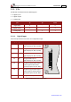
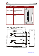
3.11.1. Digital Input
Each of the pins below can function as an independent input.
Pin (J1) Signal Function Pin Positions
9 IN1 Programmable input 1
(general purpose, RLS, FLS, INH)
10 IN2 Programmable input 2
(general purpose, RLS, FLS, INH)
11 IN3 Programmable input 3
(general purpose, RLS, FLS, INH)
12 IN4 Programmable input 4
(general purpose, RLS, FLS, INH)
13 IN5 Hi-Speed Programmable input 5
(event capture, Main Home,
general purpose, RLS, FLS, INH)
14 IN6 Hi-Speed Programmable input 6
(event capture, Auxiliary Home,
general purpose, RLS, FLS, INH)
15 INRET Programmable input return
Table 8: Digital Input Pin Assignments