
Installation Guide


Whistle and Tweeter Installation Guide Installation
MAN-WHTWIG (Ver. 1.604)
www.elmomc.com
30
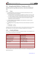
3.9. Main Feedback
The Main Feedback port is used to transfer feedback data from the motor to the drive. In order
to copy the setup to other drives, the phase order on all copy drives must be the same.
The Whistle and Tweeter can accept any one the following devices as a main feedback
mechanism:
• Incremental encoder only
• Incremental encoder with digital Hall sensors
• Digital Hall sensors only
• Interpolated Analog (Sine/Cosine) encoder (option)
• Resolver (option)
• Tachometer (option)
• Potentiometer (option)
Incremental
Encoder
Interpolated
Analog Encoder
Resolver Tachometer and
Potentiometer
WHI-XX/YYY_
TWE- XX/YYY _
WHI- XX/YYYI
TWE- XX/YYYI
WHI- XX/YYYR
TWE- XX/YYYR
WHI- XX/YYYT
TWE- XX/YYYT
Pin (J2)
Signal
Function
Signal
Function
Signal
Function
Signal
Function
13 HC
Hall sensor C
input
HC
Hall sensor C
input
NC - HC
Hall sensor C
input
11 HA
Hall sensor A
input
HA
Hall sensor A
input
NC - HA
Hall sensor A
input
2 SUPRET Supply return SUPRET Supply return SUPRET Supply return SUPRET Supply return
1 +5V
Encoder/Hall
+5V supply
+5V
Encoder/Hall
+5V supply
+5V
Encoder/Hall
+5V supply
+5V
Encoder/Hall +5V
supply
6 CHA-
Channel A
complement
A-
Sine A
complement
S3
Sine A
complement
Tac 1-
Tacho Input 1
Neg. (20 V max)
5 CHA Channel A A+ Sine A S1 Sine A Tac 1+
Tacho Input 1
Pos. (20 V max)
10 INDEX-
Index
complement
R-
Reference
complement
R2
Vref complmnt
f= 1/TS, 50 mA
Maximum
NC -
9 INDEX Index R+ Reference R1
Vref f=1/TS, 50
mA Max.
POT
Potentiometer
Input (5 V Max)
12 HB
Hall sensor B
input
HB
Hall sensor B
input
NC - HB
Hall sensor B
input
8 CHB-
Channel B
complement
B-
Cosine B
complement
S4
Cosine B
complement
Tac 2-
Tacho Input 2
Neg. (50 V max)
7 CHB Channel B B+ Cosine B S2 Cosine B Tac 2+
Tacho Input 2
Pos. (50 V max)
3 ANALIN+ is used for Analog Input
4 ANALIN- is used for Analog Input
14 LED_2_OUT (AOKLED cathode) is used for LED indication
15 LED_1_OUT (AOKLED anode) is used for LED indication
Table 4: Main Feedback Pin Assignments