
Installation Guide


Whistle and Tweeter Installation Guide Installation
MAN-WHTWIG (Ver. 1.604)
www.elmomc.com
17
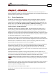
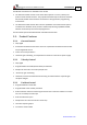
The part number at the top gives the type designation as follows:
Maximum DC
Operating Voltage
Continuous Current
(Amps)
Version:
Blank = Standard
A = Advanced
Feedback:
Blank =
Incremental
Encoder
and/or Halls
R = Resolver
WHI-A
XX/YYYR
T =
Tachometer &
Potentiometer
I =
Interpolated
Analog
Encoder
Maximum DC
Operating Voltage
Continuous Current
(Amps)
Version :
Blank = Standard
A = Advanced
Feedback:
Blank = Incremental
Encoder
and/or Halls
R = Resolver
TWE- A
XX/YYY R
T =
Tachometer &
Potentiometer
I = Interpolated
Analog
Encoder
Verify that the Whistle or Tweeter type is the one that you ordered, and ensure that the
voltage meets your specific requirements.
3.3. Connectors
The Whistle and Tweeter have nine connectors.
3.3.1. Connector Types
Port Pins Type Function Connector Location
J1 2x11 2 mm pitch
0.51 mm sq
I/O, COMM,
Auxiliary Feedback
J2 15 Main Feedback,
Analog Input, LED
M1 2 Motor power output 1
M2 2 Motor power output 2
M3 2 Motor power output 3
PE 2 Protective earth
PR 2 Power input return
VP+ 2 Positive power input
VL 1 Auxiliary power input
Table 1: Connector Types