
Installation Guide Owner manual


DC Whistle Installation Guide Technical Specifications
MAN-DCWHIIG (Ver. 1.101)
www.elmomc.com
62
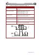
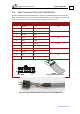
4.7.9. Auxiliary Feedback Port (input mode YA[4]= 2, 0)
Feature Details
Encoder input,
pulse and direction input
A, B, Index
Differential
Output current capability V
In
Low: 0 V < V
IL
< 0.8 V
V
In
High: 2 V < V
IH
< 5 V
Maximum absolute voltage: 0 < V
In
< 5.5 V
Input current: ±1 µA
Encoder/Hall supply voltage
5 V + 5%
Maximum encoder supply current 200 mA
Available as options Differential Encoder inputs
Differential Pulse and Direction inputs
Edge separation between A & B Programmable number of clocks to allow adequate
noise filtering at remote receiver of emulated
encoder signals
Index (marker) Length of pulse is one quadrature (one quarter of
an encoder cycle) and synchronized to A&B
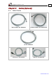
Figure 28: Auxiliary Feedback - Encoder Phase Diagram