
Installation Guide Owner manual

DC Whistle Installation Guide Installation
MAN-DCWHIIG (Ver. 1.101)
www.elmomc.com
27
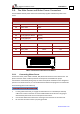
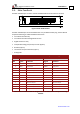
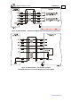
Resolver Tachometer and Potentiometer
DC-WHI-XX/YYYR DC-WHI XX/YYYT
Pin Signal Function Signal Function
1 +5V Encoder/Hall +5V supply +5V Encoder/Hall +5V supply
2 SUPRET Supply return SUPRET Supply return
3 S1 Sine A Tac 1+ Tacho Input 1 Pos. (20 V max)
4 S3 Sine A complement Tac 1- Tacho Input 1 Neg. (20 V max)
5 S2 Cosine B Tac 2+ Tacho Input 2 Pos. (50 V max)
6 S4 Cosine B complement Tac 2- Tacho Input 2 Neg. (50 V max)
7 R1 Vref f=1/TS, 50 mA Max. POT Potentiometer Input
8 R2 Vref complement
f= 1/TS, 50 mA Max
NC -
9 NC - HA Hall sensor A input
10 NC - HB Hall sensor B input
11 NC - HC Hall sensor C input
12 SUPRET Supply return SUPRET Supply return
Table 8: Main Feedback Cable Pin Assignment for Resolver, Tachometer &Potentiometer
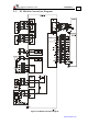
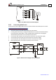
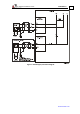
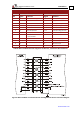
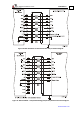
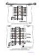
Figure 9: Main Feedback- Incremental Encoder with Digital Halls Sensors Connection Diagram