
Installation Guide Owner manual

DC Whistle Installation Guide Installation
MAN-DCWHIIG (Ver. 1.101)
www.elmomc.com
26
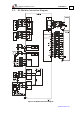
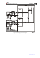
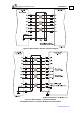
3.9. Main Feedback
The Main Feedback port is used to transfer Feedback data from the motor to the drive.
Figure 8: Main Feedback Port
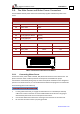
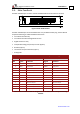
The Main Feedback port on the DC Whistle has a 12-pin Molex Header plug. The DC Whistle
accepts the following as a Main Feedback mechanism:
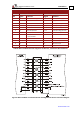
• Incremental encoder only
• Incremental encoder with digital hall sensors
• Digital hall sensors only
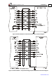
• Interpolated analog (sine/cosine) encoder (option)
• Resolver (option)
• Tachometer and potentiometer (option)
• Analog Halls
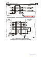
Incremental Encoder Interpolated Analog Encoder
DC-WHI-XX/YYY DC-WHI-XX/YYYI
Pin Signal Function Signal Function
1 +5V Encoder/Hall +5V supply +5V Encoder/Hall +5V supply
2 SUPRET Supply return SUPRET Supply return
3 CHA Channel A A+ Sine A
4 CHA- Channel A complement A- Sine A complement
5 CHB Channel B B+ Cosine B
6 CHB- Channel B complement B- Cosine B complement
7 INDEX Index R+ Reference
8 INDEX- Index complement R- Reference complement
9 HA Hall sensor A input HA Hall sensor A input
10 HB Hall sensor B input HB Hall sensor B input
11 HC Hall sensor C input HC Hall sensor C input
12 SUPRET Supply return SUPRET Supply return
Table 7: Main Feedback Cable Pin Assignment for Incremental and Interpolated Analog
Encoder