DC Whistle Digital Servo Drive Installation Guide July 2014 (Ver. 1.101) www.elmomc.
Notice This guide is delivered subject to the following conditions and restrictions: • This guide contains proprietary information belonging to Elmo Motion Control Ltd. Such information is supplied solely for the purpose of assisting users of the DC Whistle servo drive in its installation. • The text and graphics included in this manual are for the purpose of illustration and reference only. The specifications on which they are based are subject to change without notice.
Elmo Worldwide Head Office Elmo Motion Control Ltd. 60 Amal St., P.O. Box 3078, Petach Tikva 49516 Israel Tel: +972 (3) 929-2300 • Fax: +972 (3) 929-2322 • info-il@elmomc.com North America Elmo Motion Control Inc. 42 Technology Way, Nashua, NH 03060 USA Tel: +1 (603) 821-9979 • Fax: +1 (603) 821-9943 • info-us@elmomc.com Europe Elmo Motion Control GmbH Hermann-Schwer-Strasse 3, 78048 VS-Villingen Germany Tel: +49 (0) 7721-944 7120 • Fax: +49 (0) 7721-944 7130 • info-de@elmomc.
DC Whistle Installation Guide MAN-DCWHIIG (Ver. 1.101) Table of Contents Chapter 1: 1.1. 1.2. 1.3. 1.4. 1.5. Warnings.....................................................................................................................8 Cautions ......................................................................................................................8 Directives and Standards ............................................................................................9 CE Marking Conformance ...
DC Whistle Installation Guide Table of Contents MAN-DCWHIIG (Ver. 1.101) 3.11. I/O ............................................................................................................................ 41 3.11.1. I/O ............................................................................................................. 42 1.1.1.1 Digital Input ............................................................................. 43 1.1.1.2 Digital Output ...............................................
DC Whistle Installation Guide Table of Contents MAN-DCWHIIG (Ver. 1.101) 5.6. 5.7. Communication Cables ............................................................................................ 73 5.6.1. RS-232 Option (CBL-RJ452321) ................................................................. 73 5.6.2. CAN (CBL-RJ45CAN1) ................................................................................ 74 Guidelines for Making Your Own Cables ......................................................
DC Whistle Installation Guide 7 MAN-DCWHIIG (Ver. 1.101) Chapter 1: Safety I nform ation In order to achieve the optimum, safe operation of the DC Whistle, it is imperative that you implement the safety procedures included in this installation guide. This information is provided to protect you and to keep your work area safe when operating the DC Whistle and accompanying equipment. Please read this chapter carefully before you begin the installation process.
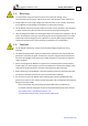
DC Whistle Installation Guide Safety Information MAN-DCWHIIG (Ver. 1.101) 1.1. Warnings • To avoid electric arcing and hazards to personnel or electrical damage, never connect/disconnect any plug or cable from the servo drive while the power source is on. • Power cables can carry a high voltage, even when the motor is not in motion. Disconnect the DC Whistle from all voltage sources before it is opened for servicing. • The DC Whistle contains grounding conduits for electric current protection.
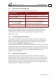
Safety Information DC Whistle Installation Guide MAN-DCWHIIG (Ver. 1.101) 1.3.
DC Whistle Installation Guide 10 MAN-DCWHIIG (Ver. 1.101) Chapter 2: I ntroduction This installation guide describes the DC Whistle and the steps for its wiring, installation and power-up. Following these guidelines ensures maximum functionality of the product and the system to which it is connected. 2.1. Product Description The DC Whistle series of servo drives enhances Elmo’s range of digital servo drives, recognized for having the highest power density and intelligence.
DC Whistle Installation Guide Introduction MAN-DCWHIIG (Ver. 1.101) 2.2. Product Features 2.2.1. Current Control • Fully digital • Sinusoidal commutation with vector control or trapezoidal commutation with encoder and/or digital Hall sensors • 12-bit current loop resolution • Automatic gain scheduling, to compensate for variations in the DC bus power supply 2.2.2.
DC Whistle Installation Guide Introduction MAN-DCWHIIG (Ver. 1.101) 2.2.5. Communication Options Depending on the application, DC Whistle users can select from two communication options: • RS-232 serial communication • CANopen for fast communication in a multi-axis distributed environment 2.2.6.
Introduction DC Whistle Installation Guide MAN-DCWHIIG (Ver. 1.101) 2.3. System Architecture Interpolated Analog Encoder Digital Inputs Main Feedback Input Digital Outputs User I/O Interface OR Incremental Encoder OR Resolver Motion Control Logic RS232 CANopen OR Tachometer & Potentiometer Communication PWM Aux. Feedback Differential Input Incremental Encoder Aux.
DC Whistle Installation Guide Introduction MAN-DCWHIIG (Ver. 1.101) 2.4. How to Use this Guide In order to install and operate your Elmo DC Whistle, you will use this manual in conjunction with a set of Elmo documentation.
DC Whistle Installation Guide 15 MAN-DCWHIIG (Ver. 1.101) Chapter 3: I nstallation The DC Whistle must be installed in a suitable environment and properly connected to its voltage supplies and the motor. 3.1. Site Requirements You can guarantee the safe operation of the DC Whistle by ensuring that it is installed in an appropriate environment.
DC Whistle Installation Guide Installation MAN-DCWHIIG (Ver. 1.101) The part number at the top gives the type designation as follows: Verify that the DC Whistle type is the one that you ordered, and ensure that the voltage meets your specific requirements. 3.3.
DC Whistle Installation Guide Installation MAN-DCWHIIG (Ver. 1.101) 3.4. Connecting the Cables 3.4.1. Wiring the DC Whistle Once the DC Whistle is mounted, you are ready to wire the device. Proper wiring, grounding and shielding are essential for ensuring safe, immune and optimal servo performance of the DC Whistle. Caution: Perform the following instructions to ensure safe and proper wiring. 1. Use twisted pair shielded cables for control, Feedback and communication connections.
Installation DC Whistle Installation Guide MAN-DCWHIIG (Ver. 1.101) The following connectors are used for wiring the DC Whistle: Type Function Main Power VP+, PR, PE Motor Power PE, M1, M2, M3 Aux. Power VL+, PR Connectors Location Motor Power Main Power Aux.
Installation DC Whistle Installation Guide MAN-DCWHIIG (Ver. 1.101) 3.5. DC Whistle Connector Types The DC Whistle has 9 connectors. Type Qty Conn. On Board Connector Main Power 1 Phoenix 3-pin Header Motor Power 1 Phoenix 4-pin Header Auxiliary Power 1 Phoenix 2-pin Header Main Feedback 1 12-Pin Molex Header I/O 1 14-Pin Molex Header Auxiliary Feedback 1 16-Pin Molex Header CAN Comm. 2 8-Pin RJ-45 Socket RS-232 Comm. 1 8-Pin RJ-45 Socket Connector Location Aux.
Installation DC Whistle Installation Guide MAN-DCWHIIG (Ver. 1.101) 3.6. Hardware Requirements The components that you will need to install your DC Whistle are: Component Qty Conn. Mating Connector Function Main Power 1 Phoenix 3-pin Plug VP+, PR, PE Motor Power 1 Phoenix 4-pin Plug PE, M1, M2, M3 Aux. Power 1 Phoenix 2-pin Plug VL+, PR Main Feedback 1 12-Pin Molex Plug Feedback I/O 1 14-Pin Molex Plug I/O Auxiliary Feedback 1 16-Pin Molex Plug Auxiliary feedback RS-232 Comm.
DC Whistle Installation Guide Installation MAN-DCWHIIG (Ver. 1.101) 3.7. DC Whistle Connection Diagram Figure 3: DC Whistle Connection Diagram www.elmomc.
Installation DC Whistle Installation Guide MAN-DCWHIIG (Ver. 1.101) 3.8. The Main Power and Motor Power Connectors The DC Whistle receives power from main and auxiliary supplies and delivers power to the motor. Pin Function Cable Main Power PE Protective earth Power PR Power return Power VP+ Pos. Power input Power Aux. Supply PR Aux. Supply Input Return Auxiliary VL+ Aux.
DC Whistle Installation Guide Installation MAN-DCWHIIG (Ver. 1.101) Figure 4: AC Motor Power Connection Diagram 3.8.2. Connecting Main Power Connect the DC power supply cable to the VP+ and PR terminals of the Main power connector. Notes for connecting the DC power supply: 1. 2. 3. 4. 5. 6. The source of the 0 to 95 VDC Power Supply must be isolated. For the greatest immunity, it is highly recommended to use twisted and shielded cables for the DC power supply cable.
DC Whistle Installation Guide Installation MAN-DCWHIIG (Ver. 1.101) 3.8.3. Low-Power Auxiliary Supply (optional) Notes for 11 to 95 VDC Auxiliary Supply connections: 1. 2. 3. 4. The source of the 11 to 95 VDC Auxiliary Supply must be isolated from the Main. For safety reasons, connect the return (common) of the Auxiliary Supply source to the closest ground near the Auxiliary Supply source. Connect the cable shield to the closest ground near the Auxiliary Supply source.
DC Whistle Installation Guide Installation MAN-DCWHIIG (Ver. 1.101) Figure 7: Shared Supply Connection Diagram www.elmomc.
Installation DC Whistle Installation Guide MAN-DCWHIIG (Ver. 1.101) 3.9. Main Feedback The Main Feedback port is used to transfer Feedback data from the motor to the drive. Figure 8: Main Feedback Port The Main Feedback port on the DC Whistle has a 12-pin Molex Header plug.
Installation DC Whistle Installation Guide MAN-DCWHIIG (Ver. 1.101) Pin Signal Resolver Tachometer and Potentiometer DC-WHI-XX/YYYR DC-WHI XX/YYYT Function Signal Function 1 +5V Encoder/Hall +5V supply +5V Encoder/Hall +5V supply 2 SUPRET Supply return SUPRET Supply return 3 S1 Sine A Tac 1+ Tacho Input 1 Pos. (20 V max) 4 S3 Sine A complement Tac 1- Tacho Input 1 Neg. (20 V max) 5 S2 Cosine B Tac 2+ Tacho Input 2 Pos.
DC Whistle Installation Guide Installation MAN-DCWHIIG (Ver. 1.101) Figure 10: Main Feedback- Incremental Encoder Only Connection Diagram Figure 11: Main Feedback – Interpolated Analog (Sine/Cosine) Encoder Connection Diagram www.elmomc.
Installation DC Whistle Installation Guide MAN-DCWHIIG (Ver. 1.101) Figure 12: Main Feedback– Resolver Connection Diagram Figure 13: Main Feedback – Tachometer Feedback with Digital Hall Sensor - Connection Diagram for Brushless Motors www.elmomc.
DC Whistle Installation Guide Installation MAN-DCWHIIG (Ver. 1.101) Figure 14: Main Feedback – Tachometer Feedback Connection Diagram for Brush Motors Figure 15: Main Feedback – Potentiometer Feedback with Digital Hall Sensor - Connection Diagram for Brushless Motors www.elmomc.
DC Whistle Installation Guide Installation MAN-DCWHIIG (Ver. 1.101) Figure 16: Main Feedback – Potentiometer Feedback Connection Diagram for Brush Motors and Voice Coils www.elmomc.
DC Whistle Installation Guide Installation MAN-DCWHIIG (Ver. 1.101) 3.10. Auxiliary Feedback (bi-directional) When using one of the Auxiliary Feedback options, the relevant functionality of the Auxiliary Feedback's ports are software selected for that option. Refer to the SimplIQ Command Reference Manual for detailed information about Auxiliary Feedback setup. The Auxiliary Feedback connector has two ports – B1 and B2.
Installation DC Whistle Installation Guide MAN-DCWHIIG (Ver. 1.101) 3.10.1. Main and Auxiliary Feedback Combinations The Main Feedback is always used in motion control devices whereas Auxiliary Feedback is often, but not always used. The Auxiliary Feedback connector has two ports (B1 and B2).
Installation DC Whistle Installation Guide 34 MAN-DCWHIIG (Ver. 1.101) Main Feedback Software Setting Auxiliary Feedback: Input YA[4] = 2 (Auxiliary Feedback: input) YA[4] = 0 (Auxiliary Feedback: input) Incremental Encoder Input Interpolated Analog (Sine/Cosine) Encoder Input Resolver Input Potentiometer Tachometer Input Typical Applications 3.10.2.
Installation DC Whistle Installation Guide MAN-DCWHIIG (Ver. 1.
DC Whistle Installation Guide Installation MAN-DCWHIIG (Ver. 1.101) Figure 17: Emulated Encoder Outputs of the Resolver or Analog Encoder Connection Diagram www.elmomc.
DC Whistle Installation Guide Installation MAN-DCWHIIG (Ver. 1.101) 3.10.3. Auxiliary Feedback - Differential Encoder Input Option (YA[4]=2) The Whistle can be used as a slave by receiving the position data (on Port B1) of the master encoder in Follower or ECAM mode. In this mode Port B2 provides differential buffered Auxiliary outputs of B1 for the next slave axis in Follower or ECAM mode.
DC Whistle Installation Guide Installation MAN-DCWHIIG (Ver. 1.101) Figure 18: Differential Auxiliary Input Option - Block Diagram Figure 19: Differential Auxiliary Input Option on Auxiliary Feedback - Connection Diagram www.elmomc.
DC Whistle Installation Guide Installation MAN-DCWHIIG (Ver. 1.101) 3.10.4. Auxiliary Feedback – Differential Pulse-and-Direction Input Option (YA[4]=0) This mode is used for input of differential pulse-and-direction position commands on Port B1. In this mode Port B2 provides differential buffered pulse-and-direction outputs of B1 for another axis.
DC Whistle Installation Guide Installation MAN-DCWHIIG (Ver. 1.101) Figure 20: Pulse-and-Direction Input Option on Auxiliary Feedback - Connection Diagram www.elmomc.
DC Whistle Installation Guide Installation MAN-DCWHIIG (Ver. 1.101) 3.11. I/O www.elmomc.
DC Whistle Installation Guide Installation MAN-DCWHIIG (Ver. 1.101) 3.11.1. I/O The DC Whistle has 6 digital inputs, 2 digital outputs and a single analog input. The I/O port has a 14-pin Molex Header plug with the following pin-outs.
DC Whistle Installation Guide Installation MAN-DCWHIIG (Ver. 1.101) 1.1.1.1 Digital Input Note: The Default Digital Input level Signal is set to 24 V (PLC). 5 V is also available (TTL). Figure 21: Digital Input Connection Diagram www.elmomc.
DC Whistle Installation Guide Installation MAN-DCWHIIG (Ver. 1.101) 1.1.1.2 Digital Output Figure 22: Digital Output Connection Diagram 3.11.2. Analog Input Figure 23: Analog Input with Single-Ended Source www.elmomc.
DC Whistle Installation Guide Installation MAN-DCWHIIG (Ver. 1.101) 3.12. Communications The communication cables use an 8-pin RJ-45 plug that connect to the RS-232 and CAN ports on the DC Whistle. The communication interface may differ according to the user’s hardware. The DC Whistle can communicate using the following options: • RS-232, full duplex • CAN RS-232 communication requires a standard, commercial 3-core null-modem cable connected from the DC Whistle to a serial interface on the PC.
DC Whistle Installation Guide Installation MAN-DCWHIIG (Ver. 1.101) Figure 24: RS-232 Connection Diagram www.elmomc.
DC Whistle Installation Guide Installation MAN-DCWHIIG (Ver. 1.101) 3.12.2. CAN Communication Notes for connecting the CAN communication cable: 1. Use 26 or 28 AWG twisted pair shielded cables. For best results, the shield should have aluminum foil and be covered by copper braid with a drain wire Connect the shield to the ground of the host (PC). Usually, this connection is soldered internally inside the connector at the PC end. You can use the drain wire to facilitate connection.
DC Whistle Installation Guide Installation MAN-DCWHIIG (Ver. 1.101) Figure 25: CAN Network Connection Diagram www.elmomc.
DC Whistle Installation Guide Installation MAN-DCWHIIG (Ver. 1.101) 3.13. Powering Up After the cables have been connected to their devices, the DC Whistle is ready to be powered up. Caution: Before applying power, ensure that the DC supply is within the range specified and that the proper plus-minus connections are in order. 3.14. Initializing the System After the DC Whistle has been connected and mounted, the system must be set up and initialized.
DC Whistle Installation Guide 50 MAN-DCWHIIG (Ver. 1.101) Chapter 4: Technical Specifications This chapter provides detailed technical information regarding the DC Whistle. This includes its dimensions, power ratings, the environmental conditions under which it can be used, the standards to which it complies and other specifications. 4.1. Features The DC Whistle’s features determine how it controls motion, as well as how it processes host commands, feedback and other input.
DC Whistle Installation Guide Technical Specifications MAN-DCWHIIG (Ver. 1.
DC Whistle Installation Guide Technical Specifications MAN-DCWHIIG (Ver. 1.101) 4.2. • Software error handling • Software-based Status reporting • Built-In Protection Available for a large number of fault conditions Protection against: 4.3.
Technical Specifications DC Whistle Installation Guide 53 MAN-DCWHIIG (Ver. 1.101) 4.4. Physical Specifications Feature Units Weight Dimensions All Types g (oz) 55 g (1.94 oz) mm (in) 115 x 75 x 25.8 mm (4.53" x 2.95" x 1.02") Mounting method PCB mount 4.5. Power Ratings Feature Units 1/60 2.5/60 5/60 10/60 Minimum supply voltage VDC 8.5 12 Nominal supply voltage VDC 48 85 Maximum supply voltage VDC 59 95 Auxiliary Power supply VDC 11 – 95 VDC (up to 2.5 VA inc.
Technical Specifications DC Whistle Installation Guide MAN-DCWHIIG (Ver. 1.
Technical Specifications DC Whistle Installation Guide MAN-DCWHIIG (Ver. 1.101) 4.6. Control Specifications 4.6.1.
Technical Specifications DC Whistle Installation Guide MAN-DCWHIIG (Ver. 1.101) 4.6.2.
Technical Specifications DC Whistle Installation Guide MAN-DCWHIIG (Ver. 1.101) 4.7. Feedbacks The DC Whistle can receive and process feedback input from diverse types of devices. 4.7.1.
Technical Specifications DC Whistle Installation Guide MAN-DCWHIIG (Ver. 1.101) Feature Details Single ended inputs Built in hysteresis for noise immunity Input voltage Nominal operating range: 0 V < VIn_Hall < 5 V Maximum absolute: -1 V < VIn_Hall < 15 V High level input voltage: V InHigh > 2.5 V Low level input voltage: V InLow < 1 V Input current Sink current (when input pulled to the common): 3 mA Source current: 1.
Technical Specifications DC Whistle Installation Guide MAN-DCWHIIG (Ver. 1.101) 4.7.5. Resolver Feature Details Resolver format Sine/Cosine Differential Input resistance Differential 2.49 kΩ Resolution Programmable: 10 to 15 bits Maximum electrical frequency (RPS) 512 revolutions/sec Resolver transfer ratio 0.5 Reference frequency 1/Ts (Ts = sample time in seconds) Reference voltage Supplied by the DC Whistle Reference current Up to ±50 mA 4.7.6.
Technical Specifications DC Whistle Installation Guide MAN-DCWHIIG (Ver. 1.101) 4.7.7. Potentiometer Feature Details Potentiometer Format Single-ended Operating Voltage Range 0 to 5 V supplied by the DC Whistle Potentiometer Resistance 100 Ω to 1 kΩ … above this range, linearity is affected detrimentally Input Resistance 100 kΩ Resolution 14 Bit www.elmomc.
Technical Specifications DC Whistle Installation Guide MAN-DCWHIIG (Ver. 1.101) 4.7.8. Auxiliary Feedback Port (output mode YA[4]= 4) Feature Details Emulated output A, B, Index Differential Output current capability Maximum output current: IOH (max) = 2 mA High level output voltage: VOH > 3.0 V Minimum output current: IOL = 2 mA Low level output voltage: VOL < 0.
Technical Specifications DC Whistle Installation Guide MAN-DCWHIIG (Ver. 1.101) 4.7.9. Auxiliary Feedback Port (input mode YA[4]= 2, 0) Feature Details Encoder input, pulse and direction input A, B, Index Output current capability VIn Low: 0 V < VIL < 0.8 V VIn High: 2 V < VIH < 5 V Maximum absolute voltage: 0 < VIn < 5.
Technical Specifications DC Whistle Installation Guide MAN-DCWHIIG (Ver. 1.101) 4.8. I/Os 4.8.1. Digital Input Interface – 4/6 Digital Inputs Feature Details Type of input Optically isolated All inputs share one signal return line Input current for all inputs Iin = 7.35 mA @ Vin = 24 V Input voltage level 24 V Note: 5 V level is also available.
Technical Specifications DC Whistle Installation Guide MAN-DCWHIIG (Ver. 1.101) 4.8.2. Digital Output Interface – 2 Digital Outputs Feature Details Type of output Optically isolated Open collector and open emitter Maximum supply output (VCC) 30 V Max. output current Iout (max) (Vout = Low) Iout (max) ≤ 10 mA VOL at maximum output voltage (low level) Vout (on) ≤ 0.3 V RL The external resistor RL must be selected to limit the output current to no more than 10 mA.
Technical Specifications DC Whistle Installation Guide MAN-DCWHIIG (Ver. 1.101) 4.9. Mechanical Specifications Feature Details Mounting The DC Whistle designed for two standard mounting options: Wall Mount, along the back (can also be mounted horizontally on a metal surface) Book Shelf, along the side Overall dimensions 115 x 75 x 25.8 mm (4.53" x 2.95" x 1") Weight 273 grams (9.6 oz.) 4.10.
Technical Specifications DC Whistle Installation Guide MAN-DCWHIIG (Ver. 1.101) 4.11. Compliance with Standards Specification Details Quality Assurance ISO 9001:2008 Quality Management Design Approved IEC/EN 61800-5-1, Safety Printed wiring for electronic equipment (clearance, creepage, spacing, conductors sizing, etc.) MIL-HDBK- 217F Reliability prediction of electronic equipment (rating, de-rating, stress, etc.
Technical Specifications DC Whistle Installation Guide MAN-DCWHIIG (Ver. 1.
DC Whistle Installation Guide 68 MAN-DCWHIIG (Ver. 1.101) Chapter 5: 5.1. Cables (Optional) Cable Photos Main Feedback: CBL- HDRFB-001 Auxiliary Feedback: CBL- HDRAUX-001 I/O: CBL- HDRIO-001 RS-232 Com.: CBL-RJ452321 CAN Com.: CBL-RJ45CAN1 www.elmomc.
Cables (Optional) DC Whistle Installation Guide MAN-DCWHIIG (Ver. 1.101) 5.2. Cable Kit The cables are all 2 m in length. Each set contains the cables listed below. Additional cable kit and/or individual cables (in multiples of 10 each) are available from Elmo. Cable Application Cable Part. No. QTY Main Feedback CBL-HDRFB-001 1 Auxiliary Feedback CBL-HDRAUX-001 1 I/O CBL-HDRIO-001 1 RS-232 Communications CBL-RJ452321 1 CAN Communications CBL-RJ45CAN1 2 www.elmomc.
Cables (Optional) DC Whistle Installation Guide MAN-DCWHIIG (Ver. 1.101) 5.3. Main Feedback Cable (CBL-HDRFB-001) The Main Feedback cable (CBL-HDRFB-001) is made of a 24-AWG shielded cable with a 12-pin Molex Header socket. It connects to the Main Feedback port on the DC Whistle. It is open on its other side so that it can be connected to customer-specific motor connector.
Cables (Optional) DC Whistle Installation Guide MAN-DCWHIIG (Ver. 1.101) 5.4. Auxiliary Feedback (CBL-HDRAUX-001) The Auxiliary Feedback cable (CBL-HDRAUX-001) is made of a 24-AWG shielded cable with a 16pin Molex Header socket. It connects to the Auxiliary Feedback port on the DC Whistle.
Cables (Optional) DC Whistle Installation Guide MAN-DCWHIIG (Ver. 1.101) 5.5. I/O (CBL-HDRIO-001) The I/O cable (CBL-HDRIO-001) is made of a 24-AWG shielded cable with a 14-pin Molex Header socket. It connects to the I/O port on the DC Whistle.
Cables (Optional) DC Whistle Installation Guide MAN-DCWHIIG (Ver. 1.101) 5.6. Communication Cables The communication cables use 26-AWG twisted pair shielded cable. They are connected using an 8-pin RJ-45 plug. Elmo drives can communicate using the following options: • RS-232 full duplex • CAN 5.6.1. RS-232 Option (CBL-RJ452321) RJ-45 Pin No. Color D-type Female Pin No.
Cables (Optional) DC Whistle Installation Guide MAN-DCWHIIG (Ver. 1.101) 5.6.2. CAN (CBL-RJ45CAN1) RJ-45 Pin No. Color D-type Female Pin No. Signal Description 1 Green 7 CAN-H CAN_H bus line 2 Yellow 2 CAN_L CAN_L bus line 3 White 3 CAN_GND CAN ground 4 — — — — 5 — — — — 7 — — — — 8 — — — — Drain Wire body shield cable shield body 1 Note: The shields of the RJ-45 and D-type plugs are connected to each other through the cable braid.
Cables (Optional) DC Whistle Installation Guide MAN-DCWHIIG (Ver. 1.101) 5.7. Guidelines for Making Your Own Cables Proper wiring, grounding and shielding are essential for ensuring safe, immune and optimal servo performance of the DC Whistle. If you do not plan to use cables provided by Elmo, follow the instructions below carefully. Caution: Perform the following instructions to ensure safe and proper wiring. 1. Use twisted pair shielded cables for control, feedback and communication connections.