
User Manual


Solo Whistle Installation Guide Installation
MAN-SOLWHIIG (Ver. 1.503)
www.elmomc.com
39
3.8. I/Os
The Solo Whistle has four digital inputs, two digital outputs and one analog input.
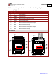
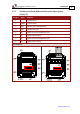
3.8.1. Digital Input
The digital input level signal can be 5 V (TTL) or 24 V (PLC).
Pin (J2) Signal Function
1 IN3 Programmable input 3 (general purpose, RLS, FLS, INH)
2 IN4 Programmable input 4 (general purpose, RLS, FLS, INH)
3 IN5 Hi-Speed Programmable input 5 (event capture, Main Home,
general purpose, RLS, FLS, INH)
4 IN6 Hi-Speed Programmable input 6 (event capture, Auxiliary Home,
general purpose, RLS, FLS, INH)
5 INRET Programmable input return
Pin Positions
Table 3: Digital Input Pin Assignments