
Installation Guide Manual


Trombone Installation Guide Installation
MAN-TROIG (Ver. 1.403)
www.elmomc.com
51
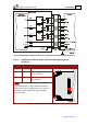
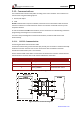
Figure 26: Differential Auxiliary Encoder Input – Highly Recommended Connection Diagram
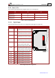
3.10.4. Auxiliary Feedback: Pulse-and-Direction Input Option
(YA[4]=0
)
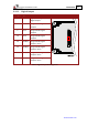
Pin (J1) Signal Function Pin Positions
32 COMRET Common return
5 DIR/CHB Direction input (push/pull 5 V
or open collector)
4 PULS/CHA Pulse input (push/pull 5 V or
open collector)
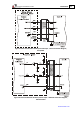
Note: The Trombone‘s Auxiliary Feedback is
single-ended (Figure 27, Figure 28 (recommended)).
When mounted on an integration board, circuitry can
be added to make it differential (Figure 29 (highly
recommended)).
Table 6: Pulse-and-Direction Pin Assignments