
Installation Guide Manual

Trombone Installation Guide Installation
MAN-TROIG (Ver. 1.403)
www.elmomc.com
47
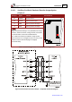
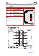
3.10.2. Auxiliary Feedback: Emulated Encoder Output Option
(YA[4]=4
)
Pin (J1) Signal Function Pin Positions
32 COMRET Common return
33 INDEXO Auxiliary index output
5 CHBO Auxiliary Channel B output
4 CHAO Auxiliary Channel A output
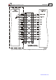
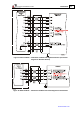
Note: The Emulated Encoder Output Option (Figure 21,
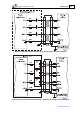
Figure 22 (recommended)) is only available when using a
resolver, absolute encoder, analog encoder, tachometer
or potentiometer as the main feedback device.
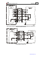
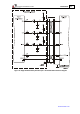
The Trombone‘s Auxiliary Feedback is single-ended.
When mounted on an integration board, circuitry can be
added to make it differential (Figure 23 (highly
recommended)).
Table 4: Emulated Single-Ended Encoder Output Pin Assignments
Figure 21: Emulated Encoder Direct Output – Acceptable Connection Diagram