
Installation Guide Manual


Trombone Installation Guide Installation
MAN-TROIG (Ver. 1.403)
www.elmomc.com
36
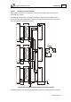
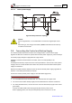
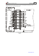
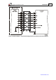
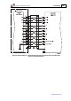
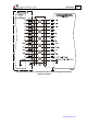
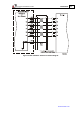
The following connection diagrams detailed in Figure 11 through Figure 20 describe the main
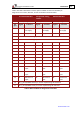
feedback connections, shown in the tables above.
Figure 11: Main Feedback – Incremental Encoder with Digital Hall Sensors Connection
Diagram