
Installation Guide Manual


Trombone Installation Guide Installation
MAN-TROIG (Ver. 1.403)
www.elmomc.com
35
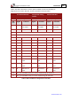
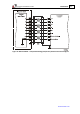
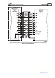
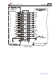
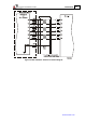
Resolver Tachometer & Potentiometer
TRO-XX/YYYR TRO-XX/YYYT
Pin Signal Function Signal Function
1 +5V
+5V Encoder/ Hall +5V supply
2 SUPRET
SUPRET Supply return
3 ANALIN+ is used for Analog Input
4 ANALIN- is used for Analog Input
5 S1 Sine A+ Tac 1+ Tacho Input 1 Pos. (20V max)
6 S3 Sine A - Tac 1- Tacho Input 1 Neg. (20 V max)
7 S2 Cosine B+ Tac 2+ Tacho Input 2 Pos. (50V max)
8 S4 Cosine B - Tac 2- Tacho Input 2 Neg. (50 V max)
9 R1 Vref f=1/TS, 50mA
Max.
POT Potentiometer Input (5V Max)
10 R2 Vref- f= 1/TS, 50 mA
Max.
NC -
11 NC
NC
11 NC
NC
13 HA
HA Hall sensor A input
14 HB
HB Hall sensor B input
13 HC
HC Hall sensor C input
16 LED_2_OUT (AOKLED cathode) is used for LED indication
17 LED_1_OUT (AOKLED anode) is used for LED indication
Table 3: Main Feedback Pin Assignments in the Resolver, Tachometer & Potentiometer