
Installation Guide Manual


Trombone Installation Guide Installation
MAN-TROIG (Ver. 1.403)
www.elmomc.com
24
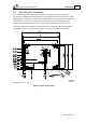
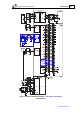
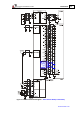
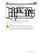
3.6. Connection Diagrams
The following three connection diagrams (Figure 3, Figure 4) show the three different ways of
connecting the power supply:
• 400 V and 800 V S models (the catalog number has an S suffix) that feature backup
functionality and require an auxiliary 24 V backup supply. The drive will not be operative
without the external 24 VDC supply.
• 400 V model without backup functionality. The drive’s internal DC/DC converter is fed from
the VP+ and VN- of the internal drive’s bus line.