
Installation Guide Manual


Trombone Installation Guide Installation
MAN-TROIG (Ver. 1.403)
www.elmomc.com
20
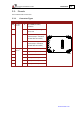
Pin (J1) Signal Function
31 +5 V Encoder +5 V supply voltage
Maximum output current: 200 mA
32 SUPRET Supply return
33 AUX PORT INDEX Auxiliary port index (bidirectional)
34 CAN_COMRET CAN communication return
35 CAN_L CAN_L bus line (dominant low)
36 CAN_H CAN_H bus line (dominant high)
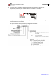
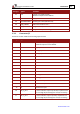
3.3.3. Connector J2
Connector J2: Main Feedback and Analog Input functions
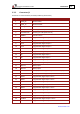
Pin (J2) Signal Function
1 +5V Encoder/Hall +5V supply voltage
Maximum output current: 200 mA
2 COMRET Supply and common return
3 ANALIN1+ Analog input 1+
4 ANALIN1- Analog input 1-
5 CHA Channel A+
6 CHA- Channel A-
7 CHB Channel B+
8 CHB- Channel B-
9 INDEX+/DATA+ Index + or Data+
10 INDEX-/DATA- Index – or Data-
11 CLOCK+ Clocking+
12 CLOCK- Clocking-
13 HA Hall sensor A input
14 HB Hall sensor B input
15 HC Hall sensor C input
16 LED_2_OUT Bi-color indication output 2 (Cathode). Implement this
pin-out usage by connecting it to a led (as necessary).
17 LED_1_OUT Bi-color indication output 1 (Anode). Implement this
pin-out usage by connecting it to a led (as necessary).