
Installation Guide Manual


Trombone Installation Guide Installation
MAN-TROIG (Ver. 1.403)
www.elmomc.com
18
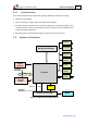
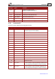
3.3. Pinouts
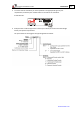
The Trombone has 9 connectors.
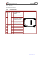
3.3.1. Connector Types
Pins Type Port Function Connector Location
2x18
2 mm pitch
0.51 mm
2
J1 I/O, COMM, Auxiliary
Feedback
17 J2 Main Feedback, Analog
Input, LED
1x2 J3.1 24 VDC Auxiliary power input
positive (Only in Trombone
models with the S suffix)
J3.2 24 VDC Auxiliary power input
return (Only in Trombone
models with the S suffix)
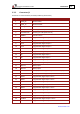
2
2.54 mm pitch
0.64 mm
2
VP+ Positive DC power input
2 VN- Negative DC power input
2 PE Protective earth
2 M1 Motor power output 1
2 M2 Motor power output 2
2 M3 Motor power output 3