
Installation Guide Instruction Manual
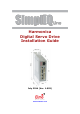
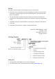


Table Of Contents
- Chapter 1: Safety Information
- Chapter 2: Introduction
- Chapter 3: Installation
- 3.1. Before You Begin
- 3.2. Unpacking the Drive Components
- 3.3. Assembling the Heatsink
- 3.4. Mounting the Harmonica
- 3.5. Connecting the Cables
- 3.5.1. Wiring the Harmonica
- 3.5.2. Connecting the Power Cables (J8)
- 3.5.3. Special Note about Disconnecting Molex Connectors
- 3.5.4. Connecting the Auxiliary Power Cable (J4)
- 3.5.5. Connecting the Feedback and Control Cables
- 3.5.5.1. Main Feedback (Feedback A) Cable (Port J3)
- 3.5.5.2. Communication Cable (Port J1)
- 3.5.5.3. I/O Cables
- 3.5.5.4. Auxiliary Feedback (Port J2)
- 3.5.5.4.a Auxiliary Feedback: Main Encoder Buffered Output or Emulated Encoder Output Option (Port J2)
- 3.5.5.4.b Auxiliary Feedback: Differential Encoder Input Option (Port J2)
- 3.5.5.4.c Auxiliary Feedback: Single-Ended Encoder Input Option (Port J2)
- 3.5.5.4.d Auxiliary Feedback: Pulse-and-Direction Input Option (Port J2)
- 3.6. Powering Up
- 3.7. Initializing the System
- Chapter 4: Technical Specifications
- 4.1. Features
- 4.2. Harmonica Dimensions
- 4.3. Power Ratings
- 4.4. Environmental Conditions
- 4.5. Harmonica Connectors
- 4.6. Auxiliary Power Supply (J4)
- 4.7. Control Specifications
- 4.8. Feedback
- 4.9. I/Os
- 4.10. Communications
- 4.11. Pulse-Width Modulation (PWM)
- 4.12. Heatsink Specifications
- 4.13. Compliance with Standards
Harmonica Installation Guide Safety Information
MAN-HARIG (Ver. 1.902)
www.elmomc.com
8
1.1. Warnings
• To avoid electric arcing and hazards to personnel and electrical contacts, never
connect/disconnect the servo drive while the power source is on.
• Power cables can carry a high voltage, even when the motor is not in motion. Disconnect
the Harmonica from all voltage sources before it is opened for servicing.
• After shutting off the power and removing the power source from your equipment, wait at
least 1 minute before touching or disconnecting parts of the equipment that are normally
loaded with electrical charges (such as capacitors or contacts). Measuring the electrical
contact points with a meter before touching the equipment is recommended.
1.2. Cautions
• The Harmonica servo drive contains hot surfaces and electrically-charged components
during operation.
• The maximum DC power supply connected to the instrument must comply with the
parameters outlined in this guide.
• The Harmonica can operate only through an isolated power source, using an isolated
transformer and a rectifier circuit. Power to this device must be supplied by DC voltage,
within the boundaries specified for the Harmonica. High voltages may damage the drive.
The DC power supply voltage range is defined in table in Section 4.3.
Safety margins must be considered in order to avoid activating the under- or over-voltage
protection against line variations and/or voltage drop under load. The transformer should
be able to deliver the required power to the drive (including peak power) without
significant voltage drops (10% maximum). While driving high-inertia loads, the power
supply circuit must be equipped with a shunt regulator; otherwise, the drive will be
disabled whenever the capacitors are charged above the maximum voltage.
• Before switching on the Harmonica, verify that all safety precautions have been observed
and that the installation procedures in this manual have been followed.
• Do not clean any of the Harmonica drive's soldering with solvent cleaning fluids of pH
greater than 7 (8 to 14). The solvent corrodes the plastic cover causing cracks and eventual
damage to the drive's PCBs.
Elmo recommends using the cleaning fluid Vigon-EFM which is pH Neutral (7).
For further technical information on this recommended cleaning fluid, select the link:
http://www.zestron.com/fileadmin/zestron.com-usa/daten/electronics/Product_TI1s/TI1-
VIGON_EFM-US.pdf