
Installation Guide Instruction Manual
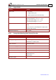
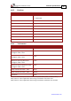
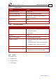


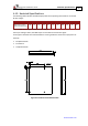


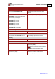
Table Of Contents
- Chapter 1: Safety Information
- Chapter 2: Introduction
- Chapter 3: Installation
- 3.1. Before You Begin
- 3.2. Unpacking the Drive Components
- 3.3. Assembling the Heatsink
- 3.4. Mounting the Harmonica
- 3.5. Connecting the Cables
- 3.5.1. Wiring the Harmonica
- 3.5.2. Connecting the Power Cables (J8)
- 3.5.3. Special Note about Disconnecting Molex Connectors
- 3.5.4. Connecting the Auxiliary Power Cable (J4)
- 3.5.5. Connecting the Feedback and Control Cables
- 3.5.5.1. Main Feedback (Feedback A) Cable (Port J3)
- 3.5.5.2. Communication Cable (Port J1)
- 3.5.5.3. I/O Cables
- 3.5.5.4. Auxiliary Feedback (Port J2)
- 3.5.5.4.a Auxiliary Feedback: Main Encoder Buffered Output or Emulated Encoder Output Option (Port J2)
- 3.5.5.4.b Auxiliary Feedback: Differential Encoder Input Option (Port J2)
- 3.5.5.4.c Auxiliary Feedback: Single-Ended Encoder Input Option (Port J2)
- 3.5.5.4.d Auxiliary Feedback: Pulse-and-Direction Input Option (Port J2)
- 3.6. Powering Up
- 3.7. Initializing the System
- Chapter 4: Technical Specifications
- 4.1. Features
- 4.2. Harmonica Dimensions
- 4.3. Power Ratings
- 4.4. Environmental Conditions
- 4.5. Harmonica Connectors
- 4.6. Auxiliary Power Supply (J4)
- 4.7. Control Specifications
- 4.8. Feedback
- 4.9. I/Os
- 4.10. Communications
- 4.11. Pulse-Width Modulation (PWM)
- 4.12. Heatsink Specifications
- 4.13. Compliance with Standards
Harmonica Installation Guide Technical Specifications
MAN-HARIG (Ver. 1.902)
www.elmomc.com
62
4.9.3. Analog Input (J7)
Feature Details Connector Location
Maximum operating differential mode
voltage
+10 V
Maximum absolute differential input voltage +16 V
Differential input resistance 3 kΩ
4.10. Communications
Specification Details Connector Location
RS-232
Signals:
• RxD , TxD , Gnd
• Full duplex, serial communication for
setup and control.
• Baud Rate of 9,600 to 57,600 bits/sec
CAN CAN bus Signals:
• CAN_H, CAN_L, CAN_GND
• Maximum Baud Rate of 1 Mbits/sec.
Version:
• DS 301 V4.01
Device Profile (drive and motion control):
• DS 402
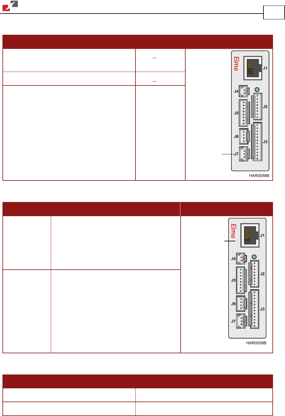
4.11. Pulse-Width Modulation (PWM)
Feature Details
PWM resolution 12-bit
PWM switching frequency on the load 2/ Ts (factory default 22 kHz on the motor)
Analog
input
Communication