
Installation Guide Instruction Manual
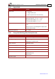
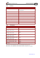
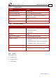


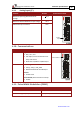
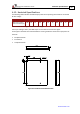


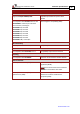
Table Of Contents
- Chapter 1: Safety Information
- Chapter 2: Introduction
- Chapter 3: Installation
- 3.1. Before You Begin
- 3.2. Unpacking the Drive Components
- 3.3. Assembling the Heatsink
- 3.4. Mounting the Harmonica
- 3.5. Connecting the Cables
- 3.5.1. Wiring the Harmonica
- 3.5.2. Connecting the Power Cables (J8)
- 3.5.3. Special Note about Disconnecting Molex Connectors
- 3.5.4. Connecting the Auxiliary Power Cable (J4)
- 3.5.5. Connecting the Feedback and Control Cables
- 3.5.5.1. Main Feedback (Feedback A) Cable (Port J3)
- 3.5.5.2. Communication Cable (Port J1)
- 3.5.5.3. I/O Cables
- 3.5.5.4. Auxiliary Feedback (Port J2)
- 3.5.5.4.a Auxiliary Feedback: Main Encoder Buffered Output or Emulated Encoder Output Option (Port J2)
- 3.5.5.4.b Auxiliary Feedback: Differential Encoder Input Option (Port J2)
- 3.5.5.4.c Auxiliary Feedback: Single-Ended Encoder Input Option (Port J2)
- 3.5.5.4.d Auxiliary Feedback: Pulse-and-Direction Input Option (Port J2)
- 3.6. Powering Up
- 3.7. Initializing the System
- Chapter 4: Technical Specifications
- 4.1. Features
- 4.2. Harmonica Dimensions
- 4.3. Power Ratings
- 4.4. Environmental Conditions
- 4.5. Harmonica Connectors
- 4.6. Auxiliary Power Supply (J4)
- 4.7. Control Specifications
- 4.8. Feedback
- 4.9. I/Os
- 4.10. Communications
- 4.11. Pulse-Width Modulation (PWM)
- 4.12. Heatsink Specifications
- 4.13. Compliance with Standards
Harmonica Installation Guide Technical Specifications
MAN-HARIG (Ver. 1.902)
www.elmomc.com
61
4.9.2. Digital Output Interface
Feature Details Connector Location
Type of output
• Optically isolated
• Open collector and open emitter
Maximum supply
output (Vcc)
30 V
Maximum output
current
Io (max) (Vout =
Low)
Iout (max) ≤ 10 mA
VOL @ maximum
output voltage (low
level)
Vout (on) ≤ 0.3 V + 0.02 * Iout (10 mA)
RL External resistor RL must be selected to limit
output current to no more than 10 mA.
(max)Io
VOLVcc
R
L
−
=
Executable time If output is set to one of the built-in
functions — Home flag, Brake or AOK —
execution is immediate upon detection:
0 < T < 4 x TS
If output is set to General output and is
executed from a program, the typical time is
approximately 0.5 msec.
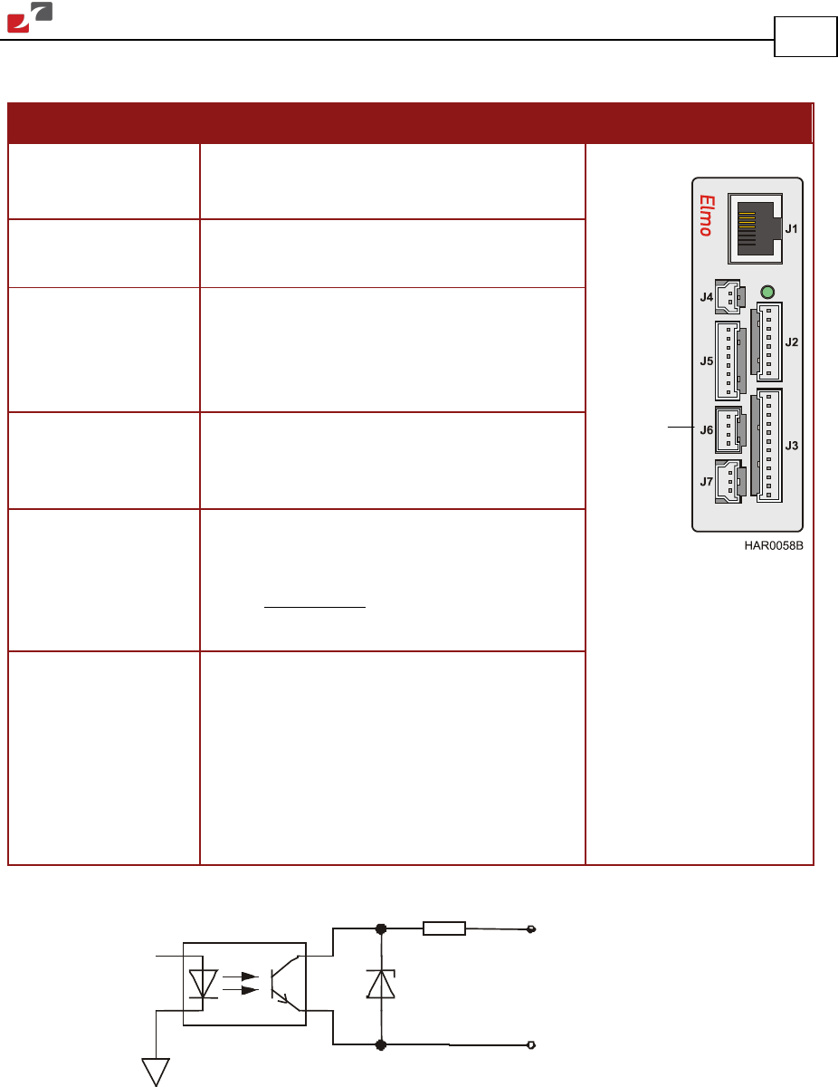
Rout = 20
Ω
33v
OUTput Ret(i)
OUTput (i)
Figure 33: Digital Output Schematic
Digital
Output