
Installation Guide Instruction Manual
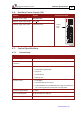
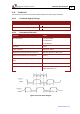
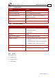

Table Of Contents
- Chapter 1: Safety Information
- Chapter 2: Introduction
- Chapter 3: Installation
- 3.1. Before You Begin
- 3.2. Unpacking the Drive Components
- 3.3. Assembling the Heatsink
- 3.4. Mounting the Harmonica
- 3.5. Connecting the Cables
- 3.5.1. Wiring the Harmonica
- 3.5.2. Connecting the Power Cables (J8)
- 3.5.3. Special Note about Disconnecting Molex Connectors
- 3.5.4. Connecting the Auxiliary Power Cable (J4)
- 3.5.5. Connecting the Feedback and Control Cables
- 3.5.5.1. Main Feedback (Feedback A) Cable (Port J3)
- 3.5.5.2. Communication Cable (Port J1)
- 3.5.5.3. I/O Cables
- 3.5.5.4. Auxiliary Feedback (Port J2)
- 3.5.5.4.a Auxiliary Feedback: Main Encoder Buffered Output or Emulated Encoder Output Option (Port J2)
- 3.5.5.4.b Auxiliary Feedback: Differential Encoder Input Option (Port J2)
- 3.5.5.4.c Auxiliary Feedback: Single-Ended Encoder Input Option (Port J2)
- 3.5.5.4.d Auxiliary Feedback: Pulse-and-Direction Input Option (Port J2)
- 3.6. Powering Up
- 3.7. Initializing the System
- Chapter 4: Technical Specifications
- 4.1. Features
- 4.2. Harmonica Dimensions
- 4.3. Power Ratings
- 4.4. Environmental Conditions
- 4.5. Harmonica Connectors
- 4.6. Auxiliary Power Supply (J4)
- 4.7. Control Specifications
- 4.8. Feedback
- 4.9. I/Os
- 4.10. Communications
- 4.11. Pulse-Width Modulation (PWM)
- 4.12. Heatsink Specifications
- 4.13. Compliance with Standards

Harmonica Installation Guide Technical Specifications
MAN-HARIG (Ver. 1.902)
www.elmomc.com
58
4.8.5. Resolver
Feature Details
Resolver format
• Sine/Cosine
• Differential
Input resistance
Differential 2.49 kΩ
Resolution Programmable: 10 to 15 bits
Maximum electrical frequency (RPS) 512 revolutions/sec
Resolver transfer ratio Meets ratio of 0.5
Reference frequency 1/Ts (Ts = sample time in kHz)
Reference voltage Supplied by the Harmonica
Reference current Up to ±50 mA
Encoder outputs
See Section 4.8.6
4.8.6. Tachometer*
Feature Details
Tachometer format Differential
Maximum operating differential
voltage for TAC1+, TAC1-
±20 V
Maximum absolute differential input
voltage for TAC1+, TAC1-
±25 V
Maximum operating differential
voltage for TAC2+, TAC2-
±50 V
Maximum absolute differential input
voltage for TAC2+, TAC2-
±60 V
Input resistance for TAC1+, TAC1- 46 kΩ
Input resistance for TAC2+, TAC2- 100 kΩ
Resolution 14 bit
* Only one Tachometer port can be used at a time (either TAC1+/TAC1- or TAC2+/TAC2-).
TAC1+/TAC1- is used in applications with having a Tachometer of less than 20 V.
TAC2+/TAC2- is used in applications with having a Tachometer of between 20 V and 50 V.