
Installation Guide Instruction Manual
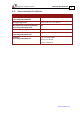
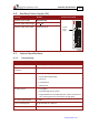
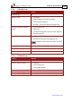
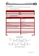
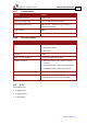

Table Of Contents
- Chapter 1: Safety Information
- Chapter 2: Introduction
- Chapter 3: Installation
- 3.1. Before You Begin
- 3.2. Unpacking the Drive Components
- 3.3. Assembling the Heatsink
- 3.4. Mounting the Harmonica
- 3.5. Connecting the Cables
- 3.5.1. Wiring the Harmonica
- 3.5.2. Connecting the Power Cables (J8)
- 3.5.3. Special Note about Disconnecting Molex Connectors
- 3.5.4. Connecting the Auxiliary Power Cable (J4)
- 3.5.5. Connecting the Feedback and Control Cables
- 3.5.5.1. Main Feedback (Feedback A) Cable (Port J3)
- 3.5.5.2. Communication Cable (Port J1)
- 3.5.5.3. I/O Cables
- 3.5.5.4. Auxiliary Feedback (Port J2)
- 3.5.5.4.a Auxiliary Feedback: Main Encoder Buffered Output or Emulated Encoder Output Option (Port J2)
- 3.5.5.4.b Auxiliary Feedback: Differential Encoder Input Option (Port J2)
- 3.5.5.4.c Auxiliary Feedback: Single-Ended Encoder Input Option (Port J2)
- 3.5.5.4.d Auxiliary Feedback: Pulse-and-Direction Input Option (Port J2)
- 3.6. Powering Up
- 3.7. Initializing the System
- Chapter 4: Technical Specifications
- 4.1. Features
- 4.2. Harmonica Dimensions
- 4.3. Power Ratings
- 4.4. Environmental Conditions
- 4.5. Harmonica Connectors
- 4.6. Auxiliary Power Supply (J4)
- 4.7. Control Specifications
- 4.8. Feedback
- 4.9. I/Os
- 4.10. Communications
- 4.11. Pulse-Width Modulation (PWM)
- 4.12. Heatsink Specifications
- 4.13. Compliance with Standards

Harmonica Installation Guide Technical Specifications
MAN-HARIG (Ver. 1.902)
www.elmomc.com
57
4.8.3. Digital Halls
Feature Details
Halls inputs
• H
A
, H
B
, H
C
.
• Single ended inputs
• Built in hysteresis for noise immunity.
Input voltage Nominal operating range: 0 V < V
In_Hall
< 5 V
Maximum absolute: -1 V < V
In_Hall
< 15 V
High level input voltage: V
InHigh
> 2.5 V
Low level input voltage: V
InLow
< 1 V
Input current Sink current (when input pulled to the common):
3 mA
Source current: 1.5 mA (designed to support open
collector Halls as well)
Maximum frequency f
MAX
: 2 kHz
4.8.4. Interpolated Analog (Sine/Cosine) Encoder
Feature Details
Analog encoder format Sine and Cosine signals
Analog input signal level Offset voltage: 2.2 V to 2.8 V
Differential, 1 V peak to peak
Input resistance
Differential 120 Ω
Maximum analog signal frequency f
MAX
: 250 kHz
Interpolation multipliers Programmable: x4 to x4096
Maximum “counts” frequency 80 mega-counts/sec “internally”
Automatic errors correction
Signals amplitude mismatch
Signals phase shift
Signals offset
Encoder outputs
See Section 4.8.6