
Installation Guide Instruction Manual
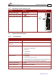
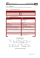
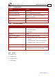

Table Of Contents
- Chapter 1: Safety Information
- Chapter 2: Introduction
- Chapter 3: Installation
- 3.1. Before You Begin
- 3.2. Unpacking the Drive Components
- 3.3. Assembling the Heatsink
- 3.4. Mounting the Harmonica
- 3.5. Connecting the Cables
- 3.5.1. Wiring the Harmonica
- 3.5.2. Connecting the Power Cables (J8)
- 3.5.3. Special Note about Disconnecting Molex Connectors
- 3.5.4. Connecting the Auxiliary Power Cable (J4)
- 3.5.5. Connecting the Feedback and Control Cables
- 3.5.5.1. Main Feedback (Feedback A) Cable (Port J3)
- 3.5.5.2. Communication Cable (Port J1)
- 3.5.5.3. I/O Cables
- 3.5.5.4. Auxiliary Feedback (Port J2)
- 3.5.5.4.a Auxiliary Feedback: Main Encoder Buffered Output or Emulated Encoder Output Option (Port J2)
- 3.5.5.4.b Auxiliary Feedback: Differential Encoder Input Option (Port J2)
- 3.5.5.4.c Auxiliary Feedback: Single-Ended Encoder Input Option (Port J2)
- 3.5.5.4.d Auxiliary Feedback: Pulse-and-Direction Input Option (Port J2)
- 3.6. Powering Up
- 3.7. Initializing the System
- Chapter 4: Technical Specifications
- 4.1. Features
- 4.2. Harmonica Dimensions
- 4.3. Power Ratings
- 4.4. Environmental Conditions
- 4.5. Harmonica Connectors
- 4.6. Auxiliary Power Supply (J4)
- 4.7. Control Specifications
- 4.8. Feedback
- 4.9. I/Os
- 4.10. Communications
- 4.11. Pulse-Width Modulation (PWM)
- 4.12. Heatsink Specifications
- 4.13. Compliance with Standards
Harmonica Installation Guide Technical Specifications
MAN-HARIG (Ver. 1.902)
www.elmomc.com
56
4.8. Feedback
The Harmonica can receive and process feedback input from diverse types of devices.
4.8.1. Feedback Supply Voltage
Feature Details
J3 (main encoder) supply voltage 5 V +5% @ 200 mA maximum
J2 (auxiliary encoder) supply voltage 5 V +5% @ 200 mA maximum
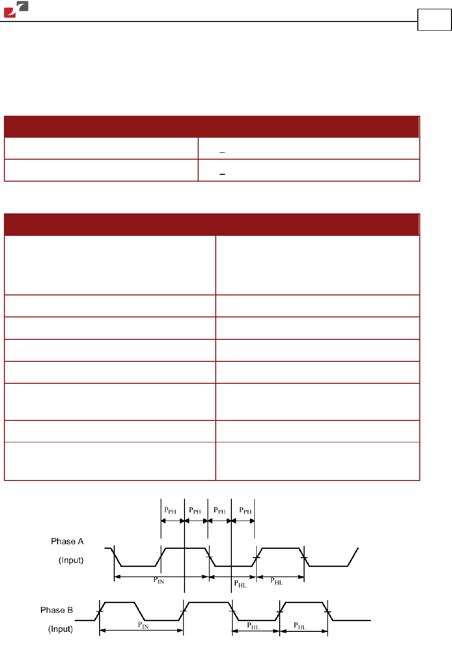
4.8.2. Incremental Encoder
Feature Details
Encoder format
• A, B and Index
• Differential
• Quadrature
Interface: RS-422
Input resistance:
Differential: 120 Ω
Maximum incremental encoder frequency Maximum absolute: 5 MHz pulses
Minimum quadrature input period (PIN) 112 nsec
Minimum quadrature input high/low period
(P
HL)
56 nsec
Minimum quadrature phase period (PPH) 28 nsec
Maximum encoder input voltage range
Common mode: ±7 V
Differential mode: ±7 V
Figure 31: Encoder Phase Diagram