
Installation Guide Instruction Manual
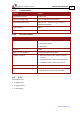

Table Of Contents
- Chapter 1: Safety Information
- Chapter 2: Introduction
- Chapter 3: Installation
- 3.1. Before You Begin
- 3.2. Unpacking the Drive Components
- 3.3. Assembling the Heatsink
- 3.4. Mounting the Harmonica
- 3.5. Connecting the Cables
- 3.5.1. Wiring the Harmonica
- 3.5.2. Connecting the Power Cables (J8)
- 3.5.3. Special Note about Disconnecting Molex Connectors
- 3.5.4. Connecting the Auxiliary Power Cable (J4)
- 3.5.5. Connecting the Feedback and Control Cables
- 3.5.5.1. Main Feedback (Feedback A) Cable (Port J3)
- 3.5.5.2. Communication Cable (Port J1)
- 3.5.5.3. I/O Cables
- 3.5.5.4. Auxiliary Feedback (Port J2)
- 3.5.5.4.a Auxiliary Feedback: Main Encoder Buffered Output or Emulated Encoder Output Option (Port J2)
- 3.5.5.4.b Auxiliary Feedback: Differential Encoder Input Option (Port J2)
- 3.5.5.4.c Auxiliary Feedback: Single-Ended Encoder Input Option (Port J2)
- 3.5.5.4.d Auxiliary Feedback: Pulse-and-Direction Input Option (Port J2)
- 3.6. Powering Up
- 3.7. Initializing the System
- Chapter 4: Technical Specifications
- 4.1. Features
- 4.2. Harmonica Dimensions
- 4.3. Power Ratings
- 4.4. Environmental Conditions
- 4.5. Harmonica Connectors
- 4.6. Auxiliary Power Supply (J4)
- 4.7. Control Specifications
- 4.8. Feedback
- 4.9. I/Os
- 4.10. Communications
- 4.11. Pulse-Width Modulation (PWM)
- 4.12. Heatsink Specifications
- 4.13. Compliance with Standards

Harmonica Installation Guide Technical Specifications
MAN-HARIG (Ver. 1.902)
www.elmomc.com
55
4.7.2. Velocity Loop
Feature Details
Controller type PI
Velocity control
• Fully digital
• Programmable PI and FFW control filters
• On-the-fly gain scheduling
• Automatic, manual and advanced manual tuning
Velocity and position feedback
options
• Incremental Encoder
• Digital Halls
• Interpolated Analog (Sine/Cosine) Encoder (optional)
• Resolver (optional)
Velocity command options
• Analog
• Internally calculated by either jogging or step
Note: All software-calculated profiles support on-the-fly
changes.
Velocity loop bandwidth <350 Hz
Velocity loop sampling time
140 to 200 µsec (x2 current loop sample time)
Velocity loop sampling rate Up to 8 kHz; default 5.5 kHz
4.7.3. Position Loop
Feature Details
Controller type
“1-2-4” PIP
Position command options
• Software
• Pulse and Direction
• Analog Potentiometer
Position loop bandwidth
<80 Hz
Position loop sampling time 280 to 400
µ
sec ( x 4 current loop sample time)
Position loop sampling rate
Up to 4 kHz; default 2.75 kHz