
Installation Guide Instruction Manual
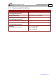
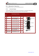
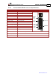
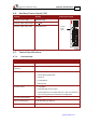
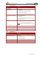

Table Of Contents
- Chapter 1: Safety Information
- Chapter 2: Introduction
- Chapter 3: Installation
- 3.1. Before You Begin
- 3.2. Unpacking the Drive Components
- 3.3. Assembling the Heatsink
- 3.4. Mounting the Harmonica
- 3.5. Connecting the Cables
- 3.5.1. Wiring the Harmonica
- 3.5.2. Connecting the Power Cables (J8)
- 3.5.3. Special Note about Disconnecting Molex Connectors
- 3.5.4. Connecting the Auxiliary Power Cable (J4)
- 3.5.5. Connecting the Feedback and Control Cables
- 3.5.5.1. Main Feedback (Feedback A) Cable (Port J3)
- 3.5.5.2. Communication Cable (Port J1)
- 3.5.5.3. I/O Cables
- 3.5.5.4. Auxiliary Feedback (Port J2)
- 3.5.5.4.a Auxiliary Feedback: Main Encoder Buffered Output or Emulated Encoder Output Option (Port J2)
- 3.5.5.4.b Auxiliary Feedback: Differential Encoder Input Option (Port J2)
- 3.5.5.4.c Auxiliary Feedback: Single-Ended Encoder Input Option (Port J2)
- 3.5.5.4.d Auxiliary Feedback: Pulse-and-Direction Input Option (Port J2)
- 3.6. Powering Up
- 3.7. Initializing the System
- Chapter 4: Technical Specifications
- 4.1. Features
- 4.2. Harmonica Dimensions
- 4.3. Power Ratings
- 4.4. Environmental Conditions
- 4.5. Harmonica Connectors
- 4.6. Auxiliary Power Supply (J4)
- 4.7. Control Specifications
- 4.8. Feedback
- 4.9. I/Os
- 4.10. Communications
- 4.11. Pulse-Width Modulation (PWM)
- 4.12. Heatsink Specifications
- 4.13. Compliance with Standards
Harmonica Installation Guide Technical Specifications
MAN-HARIG (Ver. 1.902)
www.elmomc.com
51
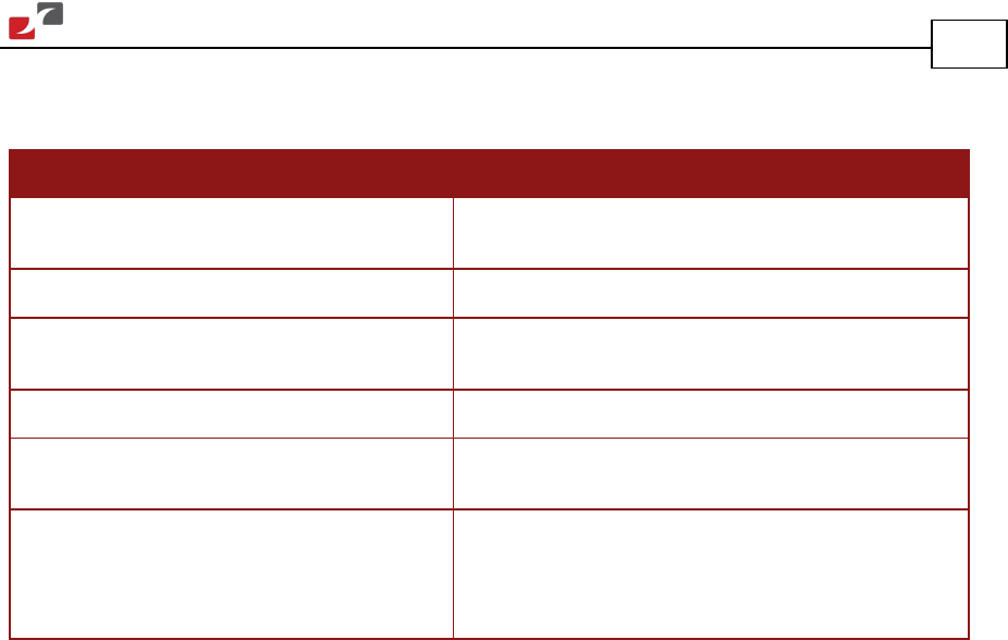
4.4. Environmental Conditions
Feature Details
Operating ambient temperature
according to IEC60068-2-2
0 °C to 40 °C (32 °F to 104 °F)
Storage temperature
-20 °C to +85 °C ( -4 °F to +185 °F)
Maximum non-condensing humidity
according to IEC60068-2-78
95%
Maximum Operating Altitude
2,000 m (6562 feet)
Mechanical Shock
according to IEC60068-2-27
15g / 11ms Half Sine
Vibration
according to IEC60068-2-6
5 Hz ≤ f ≤ 10 Hz: ±10mm
10 Hz ≤ f ≤ 57 Hz: 4G
57 Hz ≤ f ≤ 500 Hz:5G