
Installation Guide Instruction Manual
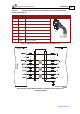
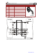
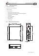
Table Of Contents
- Chapter 1: Safety Information
- Chapter 2: Introduction
- Chapter 3: Installation
- 3.1. Before You Begin
- 3.2. Unpacking the Drive Components
- 3.3. Assembling the Heatsink
- 3.4. Mounting the Harmonica
- 3.5. Connecting the Cables
- 3.5.1. Wiring the Harmonica
- 3.5.2. Connecting the Power Cables (J8)
- 3.5.3. Special Note about Disconnecting Molex Connectors
- 3.5.4. Connecting the Auxiliary Power Cable (J4)
- 3.5.5. Connecting the Feedback and Control Cables
- 3.5.5.1. Main Feedback (Feedback A) Cable (Port J3)
- 3.5.5.2. Communication Cable (Port J1)
- 3.5.5.3. I/O Cables
- 3.5.5.4. Auxiliary Feedback (Port J2)
- 3.5.5.4.a Auxiliary Feedback: Main Encoder Buffered Output or Emulated Encoder Output Option (Port J2)
- 3.5.5.4.b Auxiliary Feedback: Differential Encoder Input Option (Port J2)
- 3.5.5.4.c Auxiliary Feedback: Single-Ended Encoder Input Option (Port J2)
- 3.5.5.4.d Auxiliary Feedback: Pulse-and-Direction Input Option (Port J2)
- 3.6. Powering Up
- 3.7. Initializing the System
- Chapter 4: Technical Specifications
- 4.1. Features
- 4.2. Harmonica Dimensions
- 4.3. Power Ratings
- 4.4. Environmental Conditions
- 4.5. Harmonica Connectors
- 4.6. Auxiliary Power Supply (J4)
- 4.7. Control Specifications
- 4.8. Feedback
- 4.9. I/Os
- 4.10. Communications
- 4.11. Pulse-Width Modulation (PWM)
- 4.12. Heatsink Specifications
- 4.13. Compliance with Standards
Harmonica Installation Guide Technical Specifications
MAN-HARIG (Ver. 1.902)
www.elmomc.com
50
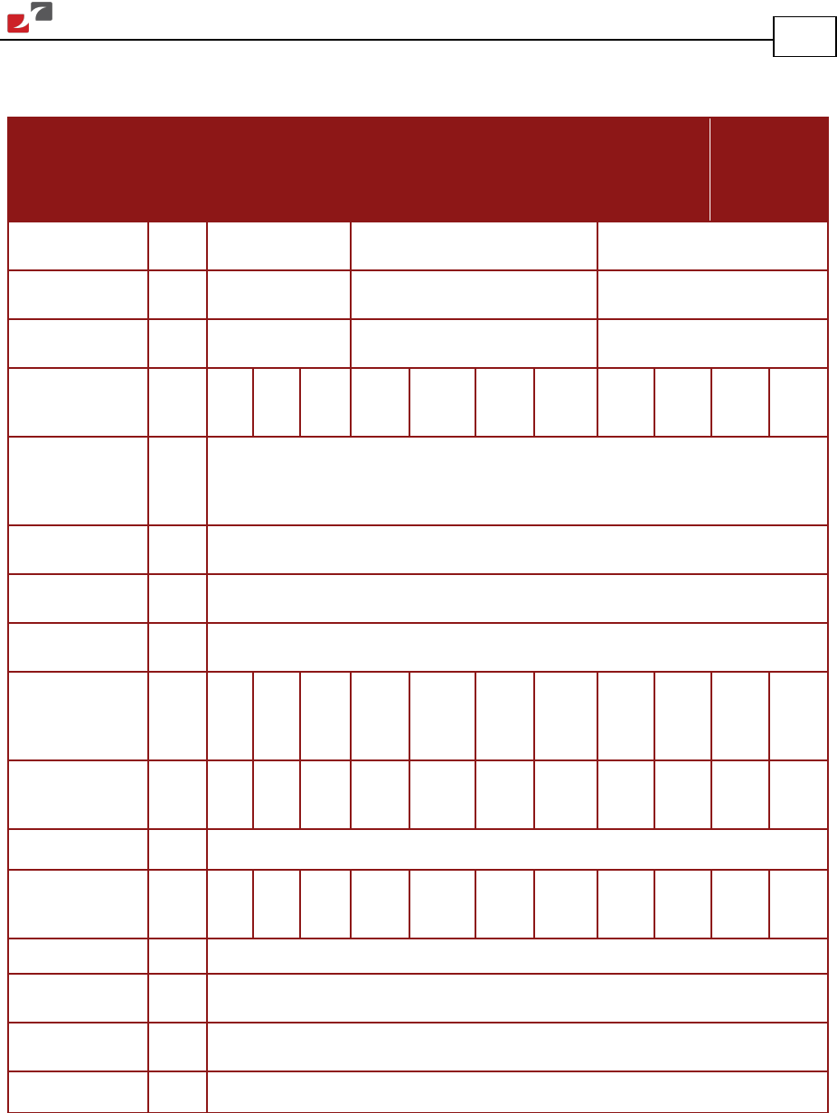
4.3. Power Ratings
Feature
Units
5/60
8/60
12/60
2/100
4/100
8/100
12/100
1/200
2/200
4/200
6/200
Minimum
supply voltage
VDC 10 20 40
Nominal
supply voltage
VDC 50 85 170
Maximum
supply voltage
VDC 59 95 195
Maximum
continuous
power output
W 250 400 650 200 320 640 1100 200 320 640 1100
Efficiency at
rated power (at
nominal
conditions)
% > 97
Maximum output
voltage
>97% of DC bus voltage at f=22 kHz
Auxiliary supply
voltage
VDC 24 ± 20%
Auxiliary power
supply
VA 8
Amplitude
sinusoidal/DC
continuous
current
A 5 8 13.3 2.5 4 8 13.3 1.25 2 4 6.6
Sinusoidal
continuous RMS
current limit (Ic)
A 3.5 5.7 9.4 1.8 2.8 5.7 9.4 0.9 1.4 2.8 4.7
Peak current limit
A 2 x Ic
RMS output
power without
heatsink
% 100 50 20 100 50 20 20 100 50 20 20
Weight g (oz) 150 g (5.3 ounces)
Dimensions mm
(in)
82 x 25.4 x 75 (3.2" x1.0" x 3.0")
Digital in/Digital
out/Analog in
6/2/1
Mounting method Wall mount (“Bookshelf”) or DIN rail