
Installation Guide Instruction Manual
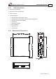
Table Of Contents
- Chapter 1: Safety Information
- Chapter 2: Introduction
- Chapter 3: Installation
- 3.1. Before You Begin
- 3.2. Unpacking the Drive Components
- 3.3. Assembling the Heatsink
- 3.4. Mounting the Harmonica
- 3.5. Connecting the Cables
- 3.5.1. Wiring the Harmonica
- 3.5.2. Connecting the Power Cables (J8)
- 3.5.3. Special Note about Disconnecting Molex Connectors
- 3.5.4. Connecting the Auxiliary Power Cable (J4)
- 3.5.5. Connecting the Feedback and Control Cables
- 3.5.5.1. Main Feedback (Feedback A) Cable (Port J3)
- 3.5.5.2. Communication Cable (Port J1)
- 3.5.5.3. I/O Cables
- 3.5.5.4. Auxiliary Feedback (Port J2)
- 3.5.5.4.a Auxiliary Feedback: Main Encoder Buffered Output or Emulated Encoder Output Option (Port J2)
- 3.5.5.4.b Auxiliary Feedback: Differential Encoder Input Option (Port J2)
- 3.5.5.4.c Auxiliary Feedback: Single-Ended Encoder Input Option (Port J2)
- 3.5.5.4.d Auxiliary Feedback: Pulse-and-Direction Input Option (Port J2)
- 3.6. Powering Up
- 3.7. Initializing the System
- Chapter 4: Technical Specifications
- 4.1. Features
- 4.2. Harmonica Dimensions
- 4.3. Power Ratings
- 4.4. Environmental Conditions
- 4.5. Harmonica Connectors
- 4.6. Auxiliary Power Supply (J4)
- 4.7. Control Specifications
- 4.8. Feedback
- 4.9. I/Os
- 4.10. Communications
- 4.11. Pulse-Width Modulation (PWM)
- 4.12. Heatsink Specifications
- 4.13. Compliance with Standards

Harmonica Installation Guide Technical Specifications
MAN-HARIG (Ver. 1.902)
www.elmomc.com
48
4.1.5. Feedback Options
• Incremental Encoder – up to 20 Mega-Counts (5 Mega-Pulse)
• Digital Halls – up to 2 kHz
• Incremental Encoder with Digital Halls for commutation – up to 20 Mega-Counts
• Absolute Encoder
• Interpolated Analog (Sine/Cosine) Encoder – up to 250 kHz
Internal Interpolation - up to X4096
Automatic Correction of amplitude mismatch, phases mismatch, signals offset
Encoder outputs, buffered, differential.
• Resolver
Programmable 10 to 15 bit resolution
Up to 512 revolutions per second (RPS)
Encoder outputs, buffered, differential
• Elmo drives provide supply voltage for all the feedback options
4.1.6. Input/Output
• Analog Inputs with up to 14-bit resolution
• Programmable digital inputs, optically isolated
Inhibit/Enable motion
Software and analog reference stop
Motion limit switches
Begin on input
Abort motion
General-purpose
Homing
• Fast event capture inputs, optically isolated
• Programmable digital outputs
Brake Control
Amplifier fault indication
General-purpose
Servo enable indication
• Buffered and differential outputs of the main encoder with up to 5 MHz pulses
• Emulated output of the resolver or interpolated analog encoder
• Fast output compare (OC), optically isolated