
Installation Guide Instruction Manual
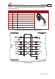
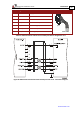
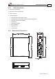
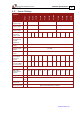
Table Of Contents
- Chapter 1: Safety Information
- Chapter 2: Introduction
- Chapter 3: Installation
- 3.1. Before You Begin
- 3.2. Unpacking the Drive Components
- 3.3. Assembling the Heatsink
- 3.4. Mounting the Harmonica
- 3.5. Connecting the Cables
- 3.5.1. Wiring the Harmonica
- 3.5.2. Connecting the Power Cables (J8)
- 3.5.3. Special Note about Disconnecting Molex Connectors
- 3.5.4. Connecting the Auxiliary Power Cable (J4)
- 3.5.5. Connecting the Feedback and Control Cables
- 3.5.5.1. Main Feedback (Feedback A) Cable (Port J3)
- 3.5.5.2. Communication Cable (Port J1)
- 3.5.5.3. I/O Cables
- 3.5.5.4. Auxiliary Feedback (Port J2)
- 3.5.5.4.a Auxiliary Feedback: Main Encoder Buffered Output or Emulated Encoder Output Option (Port J2)
- 3.5.5.4.b Auxiliary Feedback: Differential Encoder Input Option (Port J2)
- 3.5.5.4.c Auxiliary Feedback: Single-Ended Encoder Input Option (Port J2)
- 3.5.5.4.d Auxiliary Feedback: Pulse-and-Direction Input Option (Port J2)
- 3.6. Powering Up
- 3.7. Initializing the System
- Chapter 4: Technical Specifications
- 4.1. Features
- 4.2. Harmonica Dimensions
- 4.3. Power Ratings
- 4.4. Environmental Conditions
- 4.5. Harmonica Connectors
- 4.6. Auxiliary Power Supply (J4)
- 4.7. Control Specifications
- 4.8. Feedback
- 4.9. I/Os
- 4.10. Communications
- 4.11. Pulse-Width Modulation (PWM)
- 4.12. Heatsink Specifications
- 4.13. Compliance with Standards
Harmonica Installation Guide Installation
MAN-HARIG (Ver. 1.902)
www.elmomc.com
43
3.5.5.4.c Auxiliary Feedback: Single-Ended Encoder Input Option (Port J2)
Pin Signal Function Pin Positions
1 SUPRET Supply return
2 +5 V Encoder/Hall +5 V supply
voltage, 5 V @ 200 mA
3 N/A —
4 INDEX Index
5 N/A —
6 DIR/CHB Direction input (push/pull 5 V or
open collector)
7 N/A —
8 PULS/CHA Pulse input (push/pull 5 V or
open collector)
Table 13: Single-Ended Auxiliary Encoder Pin Assignment on J2
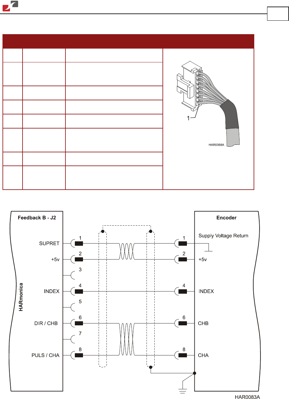
Figure 28: Single-Ended Auxiliary Encoder on J2 - Connection Diagram