
Installation Guide Instruction Manual
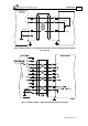
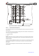
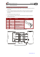
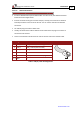
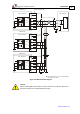
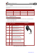
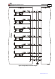
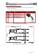
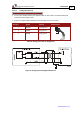
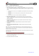
Table Of Contents
- Chapter 1: Safety Information
- Chapter 2: Introduction
- Chapter 3: Installation
- 3.1. Before You Begin
- 3.2. Unpacking the Drive Components
- 3.3. Assembling the Heatsink
- 3.4. Mounting the Harmonica
- 3.5. Connecting the Cables
- 3.5.1. Wiring the Harmonica
- 3.5.2. Connecting the Power Cables (J8)
- 3.5.3. Special Note about Disconnecting Molex Connectors
- 3.5.4. Connecting the Auxiliary Power Cable (J4)
- 3.5.5. Connecting the Feedback and Control Cables
- 3.5.5.1. Main Feedback (Feedback A) Cable (Port J3)
- 3.5.5.2. Communication Cable (Port J1)
- 3.5.5.3. I/O Cables
- 3.5.5.4. Auxiliary Feedback (Port J2)
- 3.5.5.4.a Auxiliary Feedback: Main Encoder Buffered Output or Emulated Encoder Output Option (Port J2)
- 3.5.5.4.b Auxiliary Feedback: Differential Encoder Input Option (Port J2)
- 3.5.5.4.c Auxiliary Feedback: Single-Ended Encoder Input Option (Port J2)
- 3.5.5.4.d Auxiliary Feedback: Pulse-and-Direction Input Option (Port J2)
- 3.6. Powering Up
- 3.7. Initializing the System
- Chapter 4: Technical Specifications
- 4.1. Features
- 4.2. Harmonica Dimensions
- 4.3. Power Ratings
- 4.4. Environmental Conditions
- 4.5. Harmonica Connectors
- 4.6. Auxiliary Power Supply (J4)
- 4.7. Control Specifications
- 4.8. Feedback
- 4.9. I/Os
- 4.10. Communications
- 4.11. Pulse-Width Modulation (PWM)
- 4.12. Heatsink Specifications
- 4.13. Compliance with Standards
Harmonica Installation Guide Installation
MAN-HARIG (Ver. 1.902)
www.elmomc.com
40
3.5.5.4. Auxiliary Feedback (Port J2)
For auxiliary feedback, select one of the following options:
a. Main encoder buffered outputs or emulated encoder outputs, used to provide buffered
main, or emulated, encoder signals to another controller or drive. This option can be used
when:
The Harmonica is used as a current amplifier to provide position data to the position
controller.
The Harmonica is used in velocity mode, to provide position data to the position
controller.
The Harmonica is used as a master in follower or ECAM mode.
b. Differential auxiliary inputs, for the input of position data of the master encoder in
follower or ECAM mode. This mode can also be used for differential pulse-and-direction
position commands.
c. Single-ended auxiliary input, for the input of position data of the master encoder in
follower or ECAM mode.
d. Pulse-and-direction input, for single-ended input of pulse-and-direction position
commands.
e. Differential pulse-and-direction input, for differential input of pulse-and-direction
commands.
When using one of the auxiliary feedback options, the relevant functionality of port J2 is
software selected for that option. Refer to the Harmonica Command Reference Manual for
detailed information about J2 setup.
Connect the auxiliary feedback cable into the J2 port on the front of the Harmonica, using an
8-pin, Molex plug.
Notes for connecting the auxiliary feedback cable (J2):
• Use 24, 26 or 28 AWG twisted pair shielded cables. For best results, the shield should have
aluminum foil and copper braid.
• Ground the shield near the controller.