
Installation Guide Instruction Manual
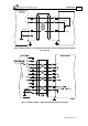
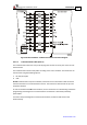
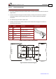
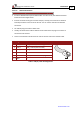
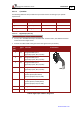
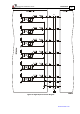
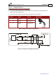
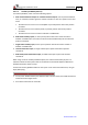
Table Of Contents
- Chapter 1: Safety Information
- Chapter 2: Introduction
- Chapter 3: Installation
- 3.1. Before You Begin
- 3.2. Unpacking the Drive Components
- 3.3. Assembling the Heatsink
- 3.4. Mounting the Harmonica
- 3.5. Connecting the Cables
- 3.5.1. Wiring the Harmonica
- 3.5.2. Connecting the Power Cables (J8)
- 3.5.3. Special Note about Disconnecting Molex Connectors
- 3.5.4. Connecting the Auxiliary Power Cable (J4)
- 3.5.5. Connecting the Feedback and Control Cables
- 3.5.5.1. Main Feedback (Feedback A) Cable (Port J3)
- 3.5.5.2. Communication Cable (Port J1)
- 3.5.5.3. I/O Cables
- 3.5.5.4. Auxiliary Feedback (Port J2)
- 3.5.5.4.a Auxiliary Feedback: Main Encoder Buffered Output or Emulated Encoder Output Option (Port J2)
- 3.5.5.4.b Auxiliary Feedback: Differential Encoder Input Option (Port J2)
- 3.5.5.4.c Auxiliary Feedback: Single-Ended Encoder Input Option (Port J2)
- 3.5.5.4.d Auxiliary Feedback: Pulse-and-Direction Input Option (Port J2)
- 3.6. Powering Up
- 3.7. Initializing the System
- Chapter 4: Technical Specifications
- 4.1. Features
- 4.2. Harmonica Dimensions
- 4.3. Power Ratings
- 4.4. Environmental Conditions
- 4.5. Harmonica Connectors
- 4.6. Auxiliary Power Supply (J4)
- 4.7. Control Specifications
- 4.8. Feedback
- 4.9. I/Os
- 4.10. Communications
- 4.11. Pulse-Width Modulation (PWM)
- 4.12. Heatsink Specifications
- 4.13. Compliance with Standards
Harmonica Installation Guide Installation
MAN-HARIG (Ver. 1.902)
www.elmomc.com
36
3.5.5.3. I/O Cables
The following table lists the I/O cables that you should connect according to your specific
requirements:
Cable Description No. Port
Digital Digital input 6 J5
Digital Digital output 2 J6
Analog Analog input 1 J7
3.5.5.3.a Digital Input (Port J5)
Notes for connecting the digital input cable:
• Use 24 , 26 or 28 AWG twisted pair shielded cable. For best results, the shield should have
aluminum foil and copper braid.
• Connect the cable shield to the ground near the signal source (controller).
Pin
(J5)
Signal Function Pin Positions
1 IN1 Programmable input 1
(general purpose, RLS, FLS, INH)
2 IN2 Programmable input 2
(general purpose, RLS, FLS, INH)
3 IN3 Programmable input 3
(general purpose, RLS, FLS, INH)
4 IN4 Programmable input 4
(general purpose, RLS, FLS, INH)
5 IN5 Programmable input 5
(event capture, Main Home,
general purpose, RLS, FLS, INH)
6 IN6 Programmable input 6
(event capture, Auxiliary Home,
general purpose, RLS, FLS, INH)
7 INRET Programmable input return
8 INRET Programmable input return
Table 8: Digital Input Cable Pin Assignment