
Installation Guide Instruction Manual
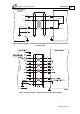
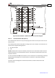
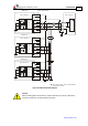
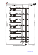
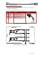
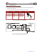
Table Of Contents
- Chapter 1: Safety Information
- Chapter 2: Introduction
- Chapter 3: Installation
- 3.1. Before You Begin
- 3.2. Unpacking the Drive Components
- 3.3. Assembling the Heatsink
- 3.4. Mounting the Harmonica
- 3.5. Connecting the Cables
- 3.5.1. Wiring the Harmonica
- 3.5.2. Connecting the Power Cables (J8)
- 3.5.3. Special Note about Disconnecting Molex Connectors
- 3.5.4. Connecting the Auxiliary Power Cable (J4)
- 3.5.5. Connecting the Feedback and Control Cables
- 3.5.5.1. Main Feedback (Feedback A) Cable (Port J3)
- 3.5.5.2. Communication Cable (Port J1)
- 3.5.5.3. I/O Cables
- 3.5.5.4. Auxiliary Feedback (Port J2)
- 3.5.5.4.a Auxiliary Feedback: Main Encoder Buffered Output or Emulated Encoder Output Option (Port J2)
- 3.5.5.4.b Auxiliary Feedback: Differential Encoder Input Option (Port J2)
- 3.5.5.4.c Auxiliary Feedback: Single-Ended Encoder Input Option (Port J2)
- 3.5.5.4.d Auxiliary Feedback: Pulse-and-Direction Input Option (Port J2)
- 3.6. Powering Up
- 3.7. Initializing the System
- Chapter 4: Technical Specifications
- 4.1. Features
- 4.2. Harmonica Dimensions
- 4.3. Power Ratings
- 4.4. Environmental Conditions
- 4.5. Harmonica Connectors
- 4.6. Auxiliary Power Supply (J4)
- 4.7. Control Specifications
- 4.8. Feedback
- 4.9. I/Os
- 4.10. Communications
- 4.11. Pulse-Width Modulation (PWM)
- 4.12. Heatsink Specifications
- 4.13. Compliance with Standards
Harmonica Installation Guide Installation
MAN-HARIG (Ver. 1.902)
www.elmomc.com
32
Figure 20: Main Feedback – Heidenhain Feedback Connection Diagram
3.5.5.2. Communication Cable (Port J1)
The communication cable uses an 8-pin RJ-45 plug that connects to the J1 port on the front of
the Harmonica.
The communication interface may differ according to the user’s hardware. The Harmonica can
communicate using the following options:
a. RS-232, full duplex
b. CAN
RS-232 communication requires a standard, commercial 3-core null-modem cable connected
from the Harmonica to a serial interface on the PC. The interface is selected and set up in the
Composer software.
In order to benefit from CAN communication, the user must have an understanding of the basic
programming and timing issues of a CAN network. The interface is electrically isolated by
optocouplers.
For ease of setup and diagnostics of CAN communication, RS-232 and CAN can be used
simultaneously.