
Installation Guide Instruction Manual


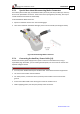


Table Of Contents
- Chapter 1: Safety Information
- Chapter 2: Introduction
- Chapter 3: Installation
- 3.1. Before You Begin
- 3.2. Unpacking the Drive Components
- 3.3. Assembling the Heatsink
- 3.4. Mounting the Harmonica
- 3.5. Connecting the Cables
- 3.5.1. Wiring the Harmonica
- 3.5.2. Connecting the Power Cables (J8)
- 3.5.3. Special Note about Disconnecting Molex Connectors
- 3.5.4. Connecting the Auxiliary Power Cable (J4)
- 3.5.5. Connecting the Feedback and Control Cables
- 3.5.5.1. Main Feedback (Feedback A) Cable (Port J3)
- 3.5.5.2. Communication Cable (Port J1)
- 3.5.5.3. I/O Cables
- 3.5.5.4. Auxiliary Feedback (Port J2)
- 3.5.5.4.a Auxiliary Feedback: Main Encoder Buffered Output or Emulated Encoder Output Option (Port J2)
- 3.5.5.4.b Auxiliary Feedback: Differential Encoder Input Option (Port J2)
- 3.5.5.4.c Auxiliary Feedback: Single-Ended Encoder Input Option (Port J2)
- 3.5.5.4.d Auxiliary Feedback: Pulse-and-Direction Input Option (Port J2)
- 3.6. Powering Up
- 3.7. Initializing the System
- Chapter 4: Technical Specifications
- 4.1. Features
- 4.2. Harmonica Dimensions
- 4.3. Power Ratings
- 4.4. Environmental Conditions
- 4.5. Harmonica Connectors
- 4.6. Auxiliary Power Supply (J4)
- 4.7. Control Specifications
- 4.8. Feedback
- 4.9. I/Os
- 4.10. Communications
- 4.11. Pulse-Width Modulation (PWM)
- 4.12. Heatsink Specifications
- 4.13. Compliance with Standards

Harmonica Installation Guide Installation
MAN-HARIG (Ver. 1.902)
www.elmomc.com
29
Figure 14: Main Feedback – Resolver Connection Diagram
2
10
9
Harmonica
Feedback A
1
Hall C
Hall B
Tacho+
Tacho-
3
11
Encoder / Hall +5v Supply
Hall / Encoder Supply / Voltage Return4
HC
HB
Tac2+
Tac2-
Tac1+
Tac1-
+5V
SUPRET
HAR0090A
12
Hall AHA
6
Tacho+
Tacho-
Up to 20Vmax
Feedback Input
Up to 50Vmax
Feedback Input
Tachometer with
Hall Sensor
5
Figure 15: Main Feedback – Tachometer Feedback with Digital Hall Sensor Connection
Diagram for Brushless Motors