
Installation Guide Instruction Manual


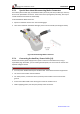


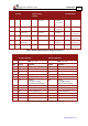


Table Of Contents
- Chapter 1: Safety Information
- Chapter 2: Introduction
- Chapter 3: Installation
- 3.1. Before You Begin
- 3.2. Unpacking the Drive Components
- 3.3. Assembling the Heatsink
- 3.4. Mounting the Harmonica
- 3.5. Connecting the Cables
- 3.5.1. Wiring the Harmonica
- 3.5.2. Connecting the Power Cables (J8)
- 3.5.3. Special Note about Disconnecting Molex Connectors
- 3.5.4. Connecting the Auxiliary Power Cable (J4)
- 3.5.5. Connecting the Feedback and Control Cables
- 3.5.5.1. Main Feedback (Feedback A) Cable (Port J3)
- 3.5.5.2. Communication Cable (Port J1)
- 3.5.5.3. I/O Cables
- 3.5.5.4. Auxiliary Feedback (Port J2)
- 3.5.5.4.a Auxiliary Feedback: Main Encoder Buffered Output or Emulated Encoder Output Option (Port J2)
- 3.5.5.4.b Auxiliary Feedback: Differential Encoder Input Option (Port J2)
- 3.5.5.4.c Auxiliary Feedback: Single-Ended Encoder Input Option (Port J2)
- 3.5.5.4.d Auxiliary Feedback: Pulse-and-Direction Input Option (Port J2)
- 3.6. Powering Up
- 3.7. Initializing the System
- Chapter 4: Technical Specifications
- 4.1. Features
- 4.2. Harmonica Dimensions
- 4.3. Power Ratings
- 4.4. Environmental Conditions
- 4.5. Harmonica Connectors
- 4.6. Auxiliary Power Supply (J4)
- 4.7. Control Specifications
- 4.8. Feedback
- 4.9. I/Os
- 4.10. Communications
- 4.11. Pulse-Width Modulation (PWM)
- 4.12. Heatsink Specifications
- 4.13. Compliance with Standards

Harmonica Installation Guide Installation
MAN-HARIG (Ver. 1.902)
www.elmomc.com
27
Incremental
Encoder
Interpolated Analog
(Sine/Cosine)
Encoder
Resolver Tachometer and
Potentiometer
7 INDEX- Index complement
R- Reference
complement
R2 Vref complement
Vref 3.5RMS
S = 1/TS, 50 mA
Max.
NC -
8 INDEX Index R+ Reference R1 Vref 3.5 vrms,
S=1/TS, 50 mA
POT Potentiometer
Input
9 CHB- Channel B
complement
B- Cosine B
complement
S4 Cosine B
complement
Tac 2- Tacho Input 2
Neg. (50 V max)
10 CHB Channel B B+ Cosine B S2 Cosine B Tac 2+ Tacho Input 2
Pos. (50 V max)
11 CHA- Channel A
complement
A- Sine A complement S3 Sine A
complement
Tac 1- Tacho Input 1
Neg. (20 V max)
12 CHA Channel A A+ Sin A S1 Sin A Tac 1+ Tacho Input 1
Pos. (20 V max)
Table 4: Main Feedback Cable Pin Assignments (Part A)
EnDat (Heidenhain)
Absolute Encoder
Stegmann
Absolute Encoder
HAR-XX/YYYA HAR-XX/YYYS
Pin Signal Function Signal Function
1 CLK - CLOCK complement HC -
2 CLK + CLOCK HB -
3 HA - HA -
4 SUPRET Supply return SUPRET Supply return
5 SUPRET Supply return SUPRET Supply return
6 +5V Encoder
+5 V supply voltage,
5 V @ 200 mA maximum
+8V Encoder
+8 V supply voltage,
8 V @ 90 mA maximum
7 DATA - Data complement DATA - Data complement
8 DATA + DATA DATA + DATA
9 B - Cos B complement B - Cos B complement
10 B + Cos B B + Cos B
11 A - Sine A complement A - Sin A
12 A + Sine A A + Sine A complement
Table 5: Main Feedback Cable Pin Assignments (Part B)