
Installation Guide Instruction Manual


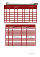


Table Of Contents
- Chapter 1: Safety Information
- Chapter 2: Introduction
- Chapter 3: Installation
- 3.1. Before You Begin
- 3.2. Unpacking the Drive Components
- 3.3. Assembling the Heatsink
- 3.4. Mounting the Harmonica
- 3.5. Connecting the Cables
- 3.5.1. Wiring the Harmonica
- 3.5.2. Connecting the Power Cables (J8)
- 3.5.3. Special Note about Disconnecting Molex Connectors
- 3.5.4. Connecting the Auxiliary Power Cable (J4)
- 3.5.5. Connecting the Feedback and Control Cables
- 3.5.5.1. Main Feedback (Feedback A) Cable (Port J3)
- 3.5.5.2. Communication Cable (Port J1)
- 3.5.5.3. I/O Cables
- 3.5.5.4. Auxiliary Feedback (Port J2)
- 3.5.5.4.a Auxiliary Feedback: Main Encoder Buffered Output or Emulated Encoder Output Option (Port J2)
- 3.5.5.4.b Auxiliary Feedback: Differential Encoder Input Option (Port J2)
- 3.5.5.4.c Auxiliary Feedback: Single-Ended Encoder Input Option (Port J2)
- 3.5.5.4.d Auxiliary Feedback: Pulse-and-Direction Input Option (Port J2)
- 3.6. Powering Up
- 3.7. Initializing the System
- Chapter 4: Technical Specifications
- 4.1. Features
- 4.2. Harmonica Dimensions
- 4.3. Power Ratings
- 4.4. Environmental Conditions
- 4.5. Harmonica Connectors
- 4.6. Auxiliary Power Supply (J4)
- 4.7. Control Specifications
- 4.8. Feedback
- 4.9. I/Os
- 4.10. Communications
- 4.11. Pulse-Width Modulation (PWM)
- 4.12. Heatsink Specifications
- 4.13. Compliance with Standards
Harmonica Installation Guide Installation
MAN-HARIG (Ver. 1.902)
www.elmomc.com
25
Pin Signal Function Pin Positions
1 +24 VDC +24 VDC auxiliary power supply
2 RET24VDC Return (common) of the 24 VDC
auxiliary power supply
Table 3: Auxiliary Power Cable Plug
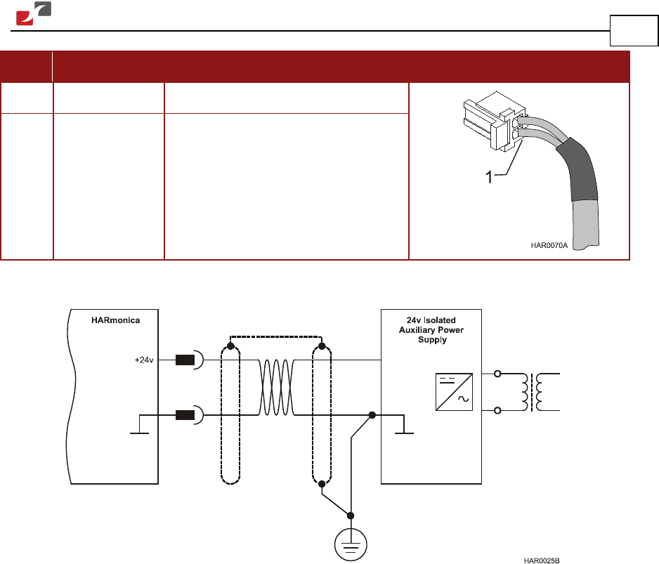
Figure 10: Auxiliary Power Supply (J4) Connection Diagram
3.5.5. Connecting the Feedback and Control Cables
The Harmonica features easy-to-use connections for all required cables. These connections
support several types of configurations and interfaces.
3.5.5.1. Main Feedback (Feedback A) Cable (Port J3)
The main feedback cable is used to transfer feedback data from the motor to the drive.
The Harmonica accepts the following as a main feedback mechanism:
• Incremental encoder only
• Incremental encoder with digital Hall sensors
• Digital Hall sensors only
• Incremental Analog (Sine/Cosine) encoder (option)
• Resolver (option)
• Tachometer and Potentiometer
• Absolute encoder