
Installation Guide Instruction Manual


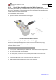


Table Of Contents
- Chapter 1: Safety Information
- Chapter 2: Introduction
- Chapter 3: Installation
- 3.1. Before You Begin
- 3.2. Unpacking the Drive Components
- 3.3. Assembling the Heatsink
- 3.4. Mounting the Harmonica
- 3.5. Connecting the Cables
- 3.5.1. Wiring the Harmonica
- 3.5.2. Connecting the Power Cables (J8)
- 3.5.3. Special Note about Disconnecting Molex Connectors
- 3.5.4. Connecting the Auxiliary Power Cable (J4)
- 3.5.5. Connecting the Feedback and Control Cables
- 3.5.5.1. Main Feedback (Feedback A) Cable (Port J3)
- 3.5.5.2. Communication Cable (Port J1)
- 3.5.5.3. I/O Cables
- 3.5.5.4. Auxiliary Feedback (Port J2)
- 3.5.5.4.a Auxiliary Feedback: Main Encoder Buffered Output or Emulated Encoder Output Option (Port J2)
- 3.5.5.4.b Auxiliary Feedback: Differential Encoder Input Option (Port J2)
- 3.5.5.4.c Auxiliary Feedback: Single-Ended Encoder Input Option (Port J2)
- 3.5.5.4.d Auxiliary Feedback: Pulse-and-Direction Input Option (Port J2)
- 3.6. Powering Up
- 3.7. Initializing the System
- Chapter 4: Technical Specifications
- 4.1. Features
- 4.2. Harmonica Dimensions
- 4.3. Power Ratings
- 4.4. Environmental Conditions
- 4.5. Harmonica Connectors
- 4.6. Auxiliary Power Supply (J4)
- 4.7. Control Specifications
- 4.8. Feedback
- 4.9. I/Os
- 4.10. Communications
- 4.11. Pulse-Width Modulation (PWM)
- 4.12. Heatsink Specifications
- 4.13. Compliance with Standards
Harmonica Installation Guide Installation
MAN-HARIG (Ver. 1.902)
www.elmomc.com
24
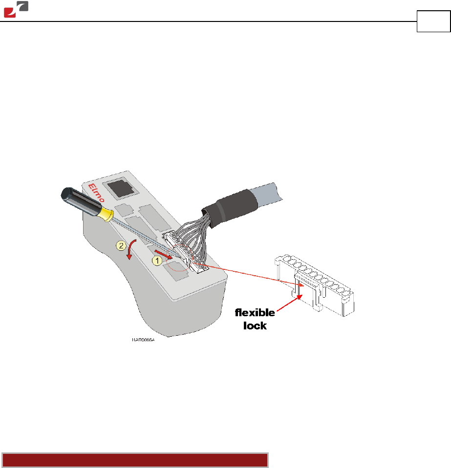
3.5.3. Special Note about Disconnecting Molex Connectors
The Auxiliary Power Cable (J4), the Feedback cables (J2 and J3) and the I/O cables (J5, J6 and J7)
all use 2 mm pitch Molex connectors. These connectors snap together quite easily, but require
a small standard screwdriver for disassembly.
To disassemble the Molex connector:
1. Slip the screwdriver into the lock: The lock disengages.
2. Twist the screwdriver downward with light pressure on the handle (see the figure below).
Figure 9: Disconnecting Molex Connectors
3.5.4. Connecting the Auxiliary Power Cable (J4)
Connect the auxiliary power supply to the J4 port on the front of the Harmonica, using a
2-pin Molex plug. Remember, you are working with DC power; be sure to exercise caution. The
required voltage is 24 VDC.
Notes for 24 VDC auxiliary power supply connections:
• Use a 24, 26 or 28 AWG twisted pair shielded cable. The shield should have copper braid.
• The source of the 24 VDC must be isolated.
• For safety reasons, connect the return (common) of the 24 VDC source to the closest
ground.
• Connect the cable shield to the closest ground near the 24 VDC source.
• Before applying power, first verify the polarity of the connection.