
Installation Guide Instruction Manual


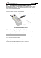


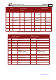


Table Of Contents
- Chapter 1: Safety Information
- Chapter 2: Introduction
- Chapter 3: Installation
- 3.1. Before You Begin
- 3.2. Unpacking the Drive Components
- 3.3. Assembling the Heatsink
- 3.4. Mounting the Harmonica
- 3.5. Connecting the Cables
- 3.5.1. Wiring the Harmonica
- 3.5.2. Connecting the Power Cables (J8)
- 3.5.3. Special Note about Disconnecting Molex Connectors
- 3.5.4. Connecting the Auxiliary Power Cable (J4)
- 3.5.5. Connecting the Feedback and Control Cables
- 3.5.5.1. Main Feedback (Feedback A) Cable (Port J3)
- 3.5.5.2. Communication Cable (Port J1)
- 3.5.5.3. I/O Cables
- 3.5.5.4. Auxiliary Feedback (Port J2)
- 3.5.5.4.a Auxiliary Feedback: Main Encoder Buffered Output or Emulated Encoder Output Option (Port J2)
- 3.5.5.4.b Auxiliary Feedback: Differential Encoder Input Option (Port J2)
- 3.5.5.4.c Auxiliary Feedback: Single-Ended Encoder Input Option (Port J2)
- 3.5.5.4.d Auxiliary Feedback: Pulse-and-Direction Input Option (Port J2)
- 3.6. Powering Up
- 3.7. Initializing the System
- Chapter 4: Technical Specifications
- 4.1. Features
- 4.2. Harmonica Dimensions
- 4.3. Power Ratings
- 4.4. Environmental Conditions
- 4.5. Harmonica Connectors
- 4.6. Auxiliary Power Supply (J4)
- 4.7. Control Specifications
- 4.8. Feedback
- 4.9. I/Os
- 4.10. Communications
- 4.11. Pulse-Width Modulation (PWM)
- 4.12. Heatsink Specifications
- 4.13. Compliance with Standards
Harmonica Installation Guide Installation
MAN-HARIG (Ver. 1.902)
www.elmomc.com
22
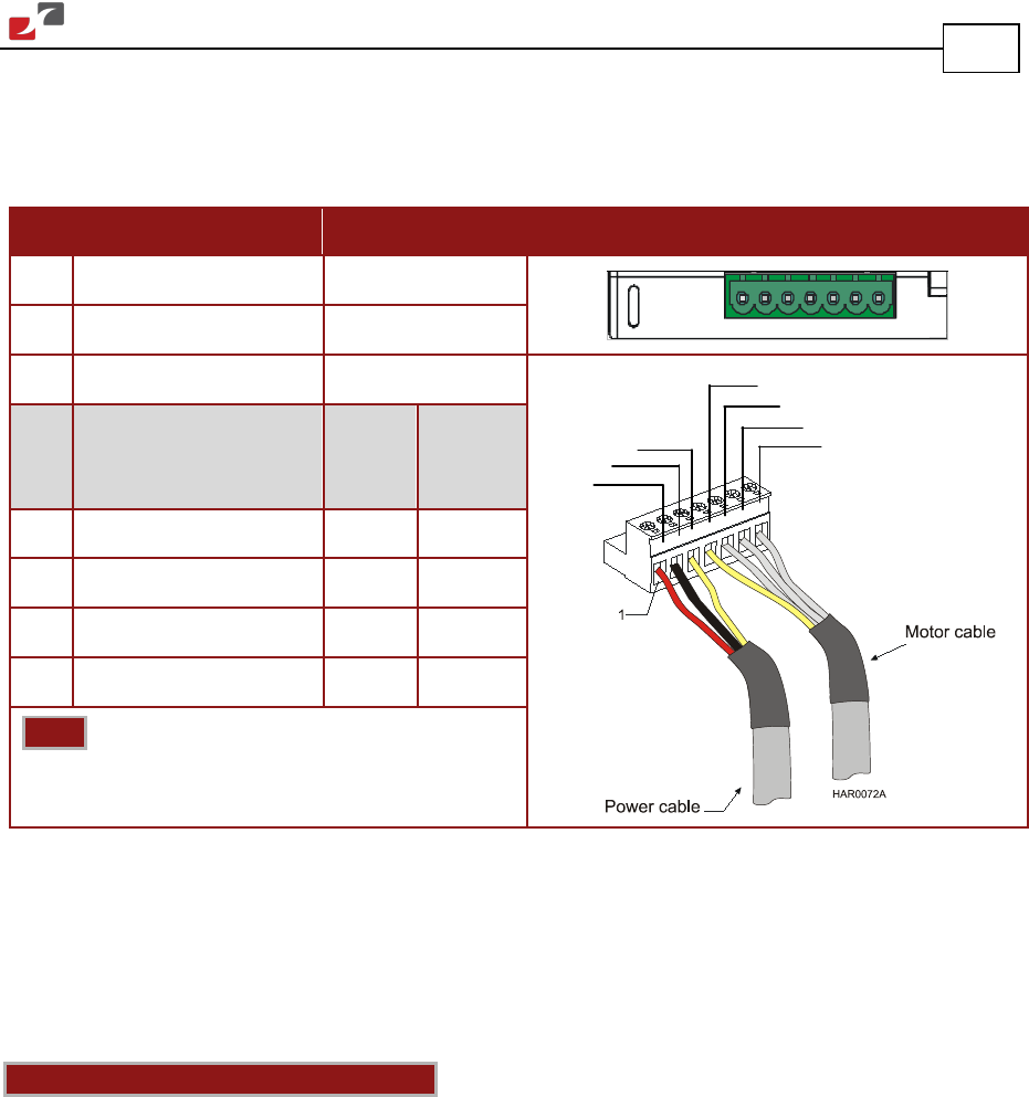
3.5.2. Connecting the Power Cables (J8)
The main power connector, which is located on the bottom of the Harmonica, includes the
following pins:
Pin Function Cable Pin Positions
VP+ Power input, positive Power
VP+ PR PE PE M1
M2 M3
PR Power input, common Power
PE Protective earth Power
AC
Motor
Cable
DC
Motor
Cable
PE Protective earth Motor Motor
M1 Motor phase Motor N/C
M2 Motor phase Motor Motor
M3 Motor phase Motor Motor
Note: When connecting several motors, all must
be wired in an identical manner.
Table 2: Connector for Main Power and Motor Cables
3.5.2.1. Connecting the Motor Cable
Connect the motor power cable to the M1, M2, M3 and PE terminals of the main power
connector. The phase connection order is arbitrary because the Composer will establish the
proper commutation automatically during setup.
Notes for connecting the motor cables:
• For best immunity, it is highly recommended to use a shielded (not twisted) cable for the
motor connection. A 4-wire shielded cable should be used. The gauge is determined by the
actual current consumption of the motor.
• Connect the shield of the cable to the closest ground connection at the motor end.
• The fourth wire should be used for the ground connection between the motor and the
second PE terminal of the Harmonica.
• Be sure that the motor chassis is properly grounded.
PR
VP+
PE
PE
M1
M2
M3