Harmonica Digital Servo Drive Installation Guide July 2014 (Ver. 1.902) www.elmomc.
Notice This guide is delivered subject to the following conditions and restrictions: • This guide contains proprietary information belonging to Elmo Motion Control Ltd. Such information is supplied solely for the purpose of assisting users of the Harmonica servo drive in its installation. • The text and graphics included in this manual are for the purpose of illustration and reference only. The specifications on which they are based are subject to change without notice.
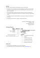
Revision History Version Details 1.0 Initial release 1.5 Apr 2008 Updated Power Ratings 1.6 Aug 2008 Updated Section 3.5.5.4: Differential pulse-and-direction input 1.7 Feb 2009 MTCR 00-100-36: Removed “Analog input command resolution” from Section 4.9.1 1.8 June 2009 Updated catalog number diagram on the Notice page (above) and in Section 3.2 1.9 July 2012 Formatted according to the new template 1.
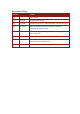
Elmo Worldwide Head Office Elmo Motion Control Ltd. 64 Gisin St., P.O. Box 463, Petach Tikva 49103 Israel Tel: +972 (3) 929-2300 • Fax: +972 (3) 929-2322 • info-il@elmomc.com North America Elmo Motion Control Inc. 42 Technology Way, Nashua, NH 03060 USA Tel: +1 (603) 821-9979 • Fax: +1 (603) 821-9943 • info-us@elmomc.com Europe Elmo Motion Control GmbH Steinkirchring 1, D-78056, Villingen-Schwenningen Germany Tel: +49 (0) 7720-85 77 60 • Fax: +49 (0) 7720-85 77 70 • info-de@elmomc.
Harmonica Installation Guide MAN-HARIG (Ver. 1.902) Table of Contents Chapter 1: 1.1. 1.2. 1.3. 1.4. 1.5. Warnings......................................................................................................................... 8 Cautions .......................................................................................................................... 8 Directives and Standards ................................................................................................
Harmonica Installation Guide Table of Contents MAN-HARIG (Ver. 1.902) 3.6. 3.7. Powering Up ................................................................................................................. 46 Initializing the System................................................................................................... 46 Chapter 4: 4.1. 4.2. 4.3. 4.4. 4.5. 4.6. 4.7. 4.8. 4.9. 4.10. 4.11. 4.12. 4.13. Technical Specifications .............................................................
Harmonica Installation Guide 7 MAN-HARIG (Ver. 1.902) Chapter 1: Safety I nform ation In order to achieve the optimum, safe operation of the Harmonica servo drive, it is imperative that you implement the safety procedures included in this installation guide. This information is provided to protect you and to keep your work area safe when operating the Harmonica and accompanying equipment. Please read this chapter carefully before you begin the installation process.
Harmonica Installation Guide Safety Information MAN-HARIG (Ver. 1.902) 1.1. Warnings • To avoid electric arcing and hazards to personnel and electrical contacts, never connect/disconnect the servo drive while the power source is on. • Power cables can carry a high voltage, even when the motor is not in motion. Disconnect the Harmonica from all voltage sources before it is opened for servicing.
Safety Information Harmonica Installation Guide MAN-HARIG (Ver. 1.902) 1.3.
Harmonica Installation Guide 10 MAN-HARIG (Ver. 1.902) Chapter 2: I ntroduction This installation guide describes the Harmonica servo drive and the steps for its wiring, installation and powering up. Following these guidelines ensures maximum functionality of the drive and the system to which it is connected. 2.1.
Harmonica Installation Guide Introduction MAN-HARIG (Ver. 1.902) 2.2.3. Position Control • Programmable PIP control filter • Programmable notch and low-pass filters • Position follower mode for monitoring the motion of the slave axis relative to a master axis, via an auxiliary encoder input • Pulse-and-direction inputs • Sample time: four times that of current loop • Fast event capturing inputs 2.2.4.
Introduction Harmonica Installation Guide MAN-HARIG (Ver. 1.902) • Tachometer and Potentiometer • Two inputs for Tachometer Feedback: • Potentiometer Feedback: • Up to ± 50 VDC Up to ±20 VDC 0 to 5 V voltage range Resistance: 100 Ω to 1000 Ω Elmo drives provide supply voltage for all the feedback options. 2.2.7.
Harmonica Installation Guide Introduction MAN-HARIG (Ver. 1.902) 2.4. How to Use this Guide In order to install and operate your Elmo Harmonica servo drive, you will use this manual in conjunction with a set of Elmo documentation.
Harmonica Installation Guide 14 MAN-HARIG (Ver. 1.902) Chapter 3: I nstallation The Harmonica must be installed in a suitable environment and properly connected to its voltage supplies and the motor. 3.1. Before You Begin 3.1.1. Site Requirements You can guarantee the safe operation of the Harmonica by ensuring that it is installed in an appropriate environment.
Installation Harmonica Installation Guide MAN-HARIG (Ver. 1.902) Component Connector Described in Section Main feedback cable J3 3.5.5.1 Auxiliary power cable J4 3.5.4 Digital input cable (if needed) J5 3.5.5.3.a Digital output cable (if needed) J6 3.5.5.3.b Analog input cable (if needed) J7 3.5.5.3.c Main power cable J8 3.5.2.2 Motor cable J8 3.5.2.2 Drawing PC for drive setup and tuning www.elmomc.
Installation Harmonica Installation Guide MAN-HARIG (Ver. 1.902) Component Connector Described in Section Drawing Motor data sheet or manual 3.2. Unpacking the Drive Components Before you begin working with the Harmonica system, verify that you have all of its components, as follows: • The Harmonica servo drive • The Composer software and software manual • The Harmonica cable kit (if ordered separately) The Harmonica is shipped in a cardboard box with Styrofoam protection.
Harmonica Installation Guide Installation MAN-HARIG (Ver. 1.902) The P/N number at the top gives the type designation as follows: 4. Verify that the Harmonica type is the one that you ordered, and ensure that the voltage meets your specific requirements. 3.3. Assembling the Heatsink When an external heatsink device is required, attach it with four screws to the left side of the Harmonica, as depicted in the following diagrams.
Installation Harmonica Installation Guide MAN-HARIG (Ver. 1.902) 3.4.1. Mounting on a DIN Rail At the top rear of the Harmonica, a horizontal groove lets you quickly and easily snap the drive onto a DIN rail in your work area. To mount the Harmonica on a DIN rail: 1. At the back of the Harmonica, push the bottom mounting strip down fully. 2. Tilt the Harmonica back towards the top part of the DIN rail. 3. Press the Harmonica down to a vertical position until it clicks onto the DIN rail. 4.
Harmonica Installation Guide Installation MAN-HARIG (Ver. 1.902) 3.5. Connecting the Cables The Harmonica has eight connectors. 3.5.1. Wiring the Harmonica Once the Harmonica is mounted, you are ready to wire the device. Proper wiring, grounding and shielding are essential for ensuring safe, immune and optimal servo performance of the Harmonica. Caution: Follow these instructions to ensure safe and proper wiring: • Use twisted and shielded wires for control, feedback and communication cables.
Installation Harmonica Installation Guide MAN-HARIG (Ver. 1.902) The following connectors are used for wiring the Harmonica.
Harmonica Installation Guide Installation MAN-HARIG (Ver. 1.902) Figure 6: Harmonica Detailed Connection Diagram with RS-232 Communication Option www.elmomc.
Installation Harmonica Installation Guide MAN-HARIG (Ver. 1.902) 3.5.2.
Harmonica Installation Guide Installation MAN-HARIG (Ver. 1.902) Figure 7: AC Motor Power Connection Diagram 3.5.2.2. Connecting the Main Power Cable Connect the main power supply cable to the VP+ and PR terminals of the main power connector. Notes for connecting the DC power supply: • Be sure to isolate the source of the DC power supply. • For best immunity, it is highly recommended to use twisted cables for the DC power supply cable. A 3-wire shielded cable should be used.
Harmonica Installation Guide Installation MAN-HARIG (Ver. 1.902) 3.5.3. Special Note about Disconnecting Molex Connectors The Auxiliary Power Cable (J4), the Feedback cables (J2 and J3) and the I/O cables (J5, J6 and J7) all use 2 mm pitch Molex connectors. These connectors snap together quite easily, but require a small standard screwdriver for disassembly. To disassemble the Molex connector: 1. Slip the screwdriver into the lock: The lock disengages. 2.
Installation Harmonica Installation Guide MAN-HARIG (Ver. 1.902) Pin Signal Function 1 +24 VDC +24 VDC auxiliary power supply 2 RET24VDC Return (common) of the 24 VDC auxiliary power supply Pin Positions Table 3: Auxiliary Power Cable Plug Figure 10: Auxiliary Power Supply (J4) Connection Diagram 3.5.5. Connecting the Feedback and Control Cables The Harmonica features easy-to-use connections for all required cables. These connections support several types of configurations and interfaces.
Installation Harmonica Installation Guide MAN-HARIG (Ver. 1.902) 26 Connect the main feedback cable from the motor to the J3 port on the front of the Harmonica, using a 12-pin, Molex plug. Notes for connecting the J3 cable: • Use 24 or 26 AWG twisted-pair shielded cables. For best results, the shield should have aluminum foil covered by copper braid. • Connect the drain wire to pin 4. The drain wire is a non-insulated wire that is in contact with parts of the cable, usually the shield.
Installation Harmonica Installation Guide 27 MAN-HARIG (Ver. 1.902) Incremental Encoder Interpolated Analog (Sine/Cosine) Encoder Resolver Tachometer and Potentiometer 7 INDEX- Index complement R- Reference complement R2 Vref complement NC Vref 3.5RMS S = 1/TS, 50 mA Max. 8 INDEX Index R+ Reference R1 Vref 3.
Harmonica Installation Guide Installation MAN-HARIG (Ver. 1.902) Figure 12: Main Feedback - Incremental Encoder Connection Diagram Figure 13: Main Feedback – Interpolated Analog (Sine/Cosine) Encoder Connection Diagram www.elmomc.
Installation Harmonica Installation Guide MAN-HARIG (Ver. 1.
Installation Harmonica Installation Guide MAN-HARIG (Ver. 1.
Harmonica Installation Guide Installation MAN-HARIG (Ver. 1.902) Potentiometer Harmonica Feedback A POT +5V SUPRET 8 6 +5v Supply 4 Voltage Return 5 HAR0093A Figure 18: Main Feedback – Potentiometer Feedback Connection Diagram for Brush Motors and Voice Coils Figure 19: Main Feedback – Stegmann Feedback Connection Diagram www.elmomc.
Harmonica Installation Guide Installation MAN-HARIG (Ver. 1.902) Figure 20: Main Feedback – Heidenhain Feedback Connection Diagram 3.5.5.2. Communication Cable (Port J1) The communication cable uses an 8-pin RJ-45 plug that connects to the J1 port on the front of the Harmonica. The communication interface may differ according to the user’s hardware. The Harmonica can communicate using the following options: a. RS-232, full duplex b.
Installation Harmonica Installation Guide MAN-HARIG (Ver. 1.902) 3.5.5.2.a RS-232 Communication Notes for connecting the RS-232 communication cable (J1 port): • Use a 26 or 28 AWG twisted pair shielded cable. The shield should have aluminum foil and copper braid. • Connect the shield to the ground of the host (PC). Usually, this connection is soldered internally inside the connector at the PC end. You can use the drain wire to facilitate connection. • The male RJ plug must have a shield cover.
Installation Harmonica Installation Guide MAN-HARIG (Ver. 1.902) 3.5.5.2.b CAN Communication Notes for connecting the CAN communication cable (J1 port): • Use 26 or 28 AWG twisted pair shielded cables. For best results, the shield should have aluminum foil and copper braid. • Connect the shield to the ground of the host (PC). Usually, this connection is soldered internally inside the connector at the PC end. You can use the drain wire to facilitate connection.
Installation Harmonica Installation Guide MAN-HARIG (Ver. 1.902) Shield of RJ connector HARmonica 1 CAN - Interface J1 CAN - Controller 6 7 1 CAN_H 120Ω 2 CAN_L 3 CAN_GND HARmonica 2 CAN - Interface J1 6 7 CAN_H CAN_L 1 2 3 HARmonica n CAN - Interface J1 6 7 CAN_H CAN_L 1 2 3 120Ω Note: If cable is long ( >5M ) it is recommended to ground at both ends Figure 22: CAN Connection Diagram Caution: When installing CAN communication, ensure that each servo drive is allocated a unique ID.
Installation Harmonica Installation Guide MAN-HARIG (Ver. 1.902) 3.5.5.3. I/O Cables The following table lists the I/O cables that you should connect according to your specific requirements: Cable Description No. Port Digital Digital input 6 J5 Digital Digital output 2 J6 Analog Analog input 1 J7 3.5.5.3.a Digital Input (Port J5) Notes for connecting the digital input cable: • Use 24 , 26 or 28 AWG twisted pair shielded cable.
Harmonica Installation Guide Installation MAN-HARIG (Ver. 1.902) Figure 23: Digital Input Connection Diagram www.elmomc.
Installation Harmonica Installation Guide MAN-HARIG (Ver. 1.902) 3.5.5.3.b Digital Output (Port J6) Notes for connecting the digital output cable: • Use 24, 26 or 28 AWG twisted pair shielded cable. For best results, the shield should have aluminum foil and copper braid. • Connect the cable shield to the ground near the controller.
Installation Harmonica Installation Guide MAN-HARIG (Ver. 1.902) 3.5.5.3.c Analog Input (Port J7) Notes for connecting the analog input cable: • Use 24, 26 or 28 AWG twisted pair shielded cable. For best results, the shield should have aluminum foil and copper braid. • Connect the cable shield to the ground near the signal source (controller).
Harmonica Installation Guide Installation MAN-HARIG (Ver. 1.902) 3.5.5.4. Auxiliary Feedback (Port J2) For auxiliary feedback, select one of the following options: a. Main encoder buffered outputs or emulated encoder outputs, used to provide buffered main, or emulated, encoder signals to another controller or drive. This option can be used when: The Harmonica is used as a current amplifier to provide position data to the position controller.
Installation Harmonica Installation Guide MAN-HARIG (Ver. 1.902) 3.5.5.4.
Installation Harmonica Installation Guide MAN-HARIG (Ver. 1.902) 3.5.5.4.
Installation Harmonica Installation Guide MAN-HARIG (Ver. 1.902) 3.5.5.4.
Installation Harmonica Installation Guide MAN-HARIG (Ver. 1.902) 3.5.5.4.
Harmonica Installation Guide Installation MAN-HARIG (Ver. 1.902) Pin Signal Function 1 SUPRET Supply return 2 +5 V N/A 3, 4 N/A — 5 DIR-/CHB- Direction low input 6 DIR/CHB Direction high input 7 PULS-/CHA- Pulse low input 8 PULS/CHA Pulse high input Pin Positions Table 15: Differential Pulse-and-Direction Auxiliary Encoder Pin Assignment on J2 Figure 30: Differential Pulse-and-Direction Auxiliary Encoder on J2 - Connection Diagram www.elmomc.
Harmonica Installation Guide Installation MAN-HARIG (Ver. 1.902) 3.6. Powering Up After the Harmonica has been mounted, check that the cables are intact. The Harmonica servo drive is then ready to be powered up. Caution: Before applying power, ensure that the DC supply is within the range specified for your specific type of Harmonica and that the proper plus-minus connections are in order. To power up the system, first switch on the auxiliary power and then the main power supply.
Harmonica Installation Guide 47 MAN-HARIG (Ver. 1.902) Chapter 4: Technical Specifications This chapter provides detailed technical information regarding the Harmonica. This includes its dimensions, power ratings, the environmental conditions under which it can be used, the standards to which it complies and other specifications. 4.1. Features The Harmonica's features determine how it controls motion, as well as how it processes host commands, feedback and other input. 4.1.1.
Harmonica Installation Guide Technical Specifications MAN-HARIG (Ver. 1.902) 4.1.5.
Harmonica Installation Guide Technical Specifications MAN-HARIG (Ver. 1.902) 4.1.7. Built-In Protection • Software error handling • Abort (hard stops and soft stops) • Status reporting • Protection against 4.2. Shorts between motor power outputs Shorts between motor power output and power input/return Failure of internal power supplies Overheating Over/Under voltage Loss of feedback Following error Current limits Harmonica Dimensions www.elmomc.
Technical Specifications Harmonica Installation Guide MAN-HARIG (Ver. 1.902) 4/200 6/200 2/200 8/100 4/100 2/100 12/60 8/60 5/60 Units Feature 1/200 Power Ratings 12/100 4.3.
Technical Specifications Harmonica Installation Guide MAN-HARIG (Ver. 1.902) 4.4.
Technical Specifications Harmonica Installation Guide MAN-HARIG (Ver. 1.902) 4.5. 52 Harmonica Connectors The following connectors are used for wiring the Harmonica. 4.5.1. Connector Types The table below shows the connector panel of the Harmonica. The Harmonica Cable Starting Kit (Cat. No. HAR-CABLEKIT) describes each connector cable in great detail. Connector Maker & No.
Harmonica Installation Guide Technical Specifications MAN-HARIG (Ver. 1.902) 4.5.2.
Harmonica Installation Guide Technical Specifications MAN-HARIG (Ver. 1.902) 4.6. Auxiliary Power Supply (J4) Feature Details Auxiliary power supply DC source only Auxiliary supply input voltage 24 V +20% Auxiliary supply input power 8 VA (maximum) 4.7. 54 Connector Location Auxiliary Power supply Control Specifications 4.7.1.
Technical Specifications Harmonica Installation Guide MAN-HARIG (Ver. 1.902) 4.7.2.
Technical Specifications Harmonica Installation Guide MAN-HARIG (Ver. 1.902) 4.8. Feedback The Harmonica can receive and process feedback input from diverse types of devices. 4.8.1. Feedback Supply Voltage Feature Details J3 (main encoder) supply voltage 5 V +5% @ 200 mA maximum J2 (auxiliary encoder) supply voltage 5 V +5% @ 200 mA maximum 4.8.2.
Technical Specifications Harmonica Installation Guide MAN-HARIG (Ver. 1.902) 4.8.3. Digital Halls Feature Details Halls inputs • HA, HB, HC. • Single ended inputs • Built in hysteresis for noise immunity. Input voltage Nominal operating range: 0 V < VIn_Hall < 5 V Maximum absolute: -1 V < VIn_Hall < 15 V High level input voltage: V InHigh > 2.5 V Low level input voltage: V InLow < 1 V Input current Sink current (when input pulled to the common): 3 mA Source current: 1.
Technical Specifications Harmonica Installation Guide MAN-HARIG (Ver. 1.902) 4.8.5. Resolver Feature Details Resolver format • Sine/Cosine • Differential Input resistance Differential 2.49 kΩ Resolution Programmable: 10 to 15 bits Maximum electrical frequency (RPS) 512 revolutions/sec Resolver transfer ratio Meets ratio of 0.5 Reference frequency 1/Ts (Ts = sample time in kHz) Reference voltage Supplied by the Harmonica Reference current Up to ±50 mA Encoder outputs See Section 4.8.
Technical Specifications Harmonica Installation Guide MAN-HARIG (Ver. 1.902) 4.8.7. Potentiometer Feature Details Potentiometer Format Single-ended Operating Voltage Range 0 to 5 V supplied by the Harmonica Potentiometer Resistance 100 Ω to 1 kΩ … above this range, linearity is affected detrimentally Input Resistance 100 kΩ Resolution 14 Bit 4.8.8.
Technical Specifications Harmonica Installation Guide MAN-HARIG (Ver. 1.902) 4.9.1. 60 Digital Input Interfaces Feature Type of input Details Connector Location • Optically isolated • Single ended Input current Iin = Vin − 6.5V 2500Ω * Iin = 2.2 mA @ Vin = 12 V Input current for high speed inputs Iin = Vin − 6.5V 1250Ω Digital Input * Iin = 4.4 mA @ Vin = 12 V High-level input voltage 12 V < Vin < 30 V, 24 V typical Low-level input voltage 0 V < Vin < 6.
Technical Specifications Harmonica Installation Guide MAN-HARIG (Ver. 1.902) 4.9.2. Digital Output Interface Feature Type of output Details Connector Location • Optically isolated • Open collector and open emitter Maximum supply output (Vcc) 30 V Maximum output current Io (max) (Vout = Low) Iout (max) ≤ 10 mA VOL @ maximum output voltage (low level) Vout (on) ≤ 0.3 V + 0.02 * Iout (10 mA) RL External resistor RL must be selected to limit output current to no more than 10 mA.
Technical Specifications Harmonica Installation Guide MAN-HARIG (Ver. 1.902) 4.9.3. Analog Input (J7) Feature Details Maximum operating differential mode voltage +10 V Maximum absolute differential input voltage +16 V Differential input resistance 3 kΩ Connector Location Analog input 4.10. Communications Specification Details RS-232 Signals: • RxD , TxD , Gnd Connector Location • Full duplex, serial communication for setup and control.
Technical Specifications Harmonica Installation Guide 63 MAN-HARIG (Ver. 1.902) 4.12. Heatsink Specifications The following table indicates the RMS output power when operating the Harmonica at nominal DC bus voltage: Harmonica 5/60 8/60 12/60 2/100 4/100 8/100 12/100 1/200 2/200 4/200 6/200 RMS output power without heatsink (%) 100 50 20 100 50 20 20 100 50 20 20 *50 V models are no longer available for new designs.
Technical Specifications Harmonica Installation Guide MAN-HARIG (Ver. 1.902) har_F_HS Figure 35: Fin-Type Heatsink Dimensions DETAIL A Har_L_HS Figure 36: L-Shaped Heatsink Dimensions www.elmomc.
Technical Specifications Harmonica Installation Guide MAN-HARIG (Ver. 1.902) 4.13. Compliance with Standards Specification Details Quality Assurance ISO 9001:2008 Quality Management Design Approved IEC/EN 61800-5-1, Safety Printed wiring for electronic equipment (clearance, creepage, spacing, conductors sizing, etc.) MIL-HDBK- 217F Reliability prediction of electronic equipment (rating, de-rating, stress, etc.
Technical Specifications Harmonica Installation Guide MAN-HARIG (Ver. 1.