
User Manual


Whistle, Bell Guitar Evaluation Board User Guide Combined Evaluation Board
MAN-EVLBRD-WHI-BEL-GUI (Ver. 1.401)
65
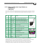
.15.1 Digital Input & DIP Switch Settings
Digital Input can be configured in one of 2 ways:
1. When the controller’s signal level is provided by an external source (user power supply)
via the General I/O connector, the 6 DIP switches (SW1, SW2) that are on must be set to
OFF (open).
2. In order to use an internal power supply for applying a high signal level to the inputs –
set the 6 DIP switches as follows: SW1-positive (5V) and SW2-return (0V) to ON (closed).
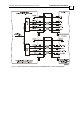
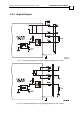
Figure 2-38: Connection Diagram of a Typical Digital Input (1 of 6 DI)
When connecting the Whistle or Bell to the Evaluation Board, the input signal is single ended
and the return power is via INRET1 (D1.1, general I/O connector).
When connecting the Guitar to the Evaluation Board, the input signal is differential. The
inputs should be connected to IN and INRET – their index number must correspond to each
other, e.g., IN1 and INRET1, etc.