Evaluation Board for the Whistle, Bell & Guitar User Guide (Also for the Hornet, Tweeter and Hawk) July 2014 (Ver. 1.401) www.elmomc.
Safety Information Whistle, Bell Guitar Evaluation Board User Guide MAN-EVLBRD-WHI-BEL-GUI (Ver. 1.401) 2 Notice This guide is delivered subject to the following conditions and restrictions: This guide contains proprietary information belonging to Elmo Motion Control Ltd. Such information is supplied solely for the purpose of assisting users of the Whistle, Bell or Guitar servo drives in their evaluation and testing.
Whistle, Bell Guitar Evaluation Board User Guide Safety Information MAN-EVLBRD-WHI-BEL-GUI (Ver. 1.401) Safety Information ..................................................................................................................... 7 .1 Warnings ............................................................................................................................ 8 .2 Cautions ................................................................................................................
Whistle, Bell Guitar Evaluation Board User Guide Safety Information MAN-EVLBRD-WHI-BEL-GUI (Ver. 1.401) .10 .9.8 Connecting the Main Power to the Bell ......................................................... 29 .9.9 Auxiliary Supply (optional) for Bell .............................................................. 30 Guitar ............................................................................................................................... 32 .10.
Whistle, Bell Guitar Evaluation Board User Guide Safety Information MAN-EVLBRD-WHI-BEL-GUI (Ver. 1.401) .19 Evaluation Board Dimensions ....................................................................................... 73 .19.1 Dimensions (Whistle) ...................................................................................... 73 .19.2 Dimensions (Bell)............................................................................................. 74 .19.3 Dimensions (Guitar) .............
Whistle, Bell Guitar Evaluation Board User Guide Safety Information MAN-EVLBRD-WHI-BEL-GUI (Ver. 1.401) .29.4.2 .30 .31 6 CAN Communication (CBL-RJ45CAN1-1)............................................................ 90 Guidelines for Making Your Own Cables .................................................................... 90 .30.1 Recommended Wire Cross Sections .............................................................. 91 .30.2 Feedback and Control Cable Assemblies ........................
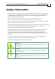
Whistle, Bell Guitar Evaluation Board User Guide Safety Information MAN-EVLBRD-WHI-BEL-GUI (Ver. 1.401) 7 Safety Information In order to achieve the optimum, safe operation of the Evaluation Board, it is imperative that you implement the safety procedures included in this installation guide. This information is provided to protect you and to keep your work area safe when operating the Evaluation Board and accompanying equipment.
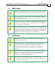
Whistle, Bell Guitar Evaluation Board User Guide Safety Information MAN-EVLBRD-WHI-BEL-GUI (Ver. 1.401) .1 Warnings To avoid electric arcing and hazards to personnel and electrical contacts, never connect/disconnect the servo drive while the power source is on. Power cables can carry a high voltage, even when the motor is not in motion. Disconnect the Evaluation Board from all voltage sources before it is opened for servicing.
Whistle, Bell Guitar Evaluation Board User Guide Safety Information MAN-EVLBRD-WHI-BEL-GUI (Ver. 1.401) .
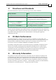
Whistle, Bell Guitar Evaluation Board User Guide Combined Evaluation Board MAN-EVLBRD-WHI-BEL-GUI (Ver. 1.401) Combined Evaluation Board .6 Introduction The combined Evaluation Board has the following advantages: 1. It can evaluate three different types of drives: • Whistle • Bell • Guitar 2. D-type, RJ and Phoenix connectors can be easily connected to the Evaluation Board. 3.
Whistle, Bell Guitar Evaluation Board User Guide Combined Evaluation Board MAN-EVLBRD-WHI-BEL-GUI (Ver. 1.401) 11 The Evaluation Board dissipates its heat by natural convection. The maximum operating ambient temperature of 0 °C to 40 °C (32 °F to 104° F) must not be exceeded. Refer to the Heat Dissipation section of the relevant installation guide for further details. .7.
Whistle, Bell Guitar Evaluation Board User Guide Combined Evaluation Board MAN-EVLBRD-WHI-BEL-GUI (Ver. 1.401) .8 12 Whistle This section explains how to connect the Whistle to the Evaluation Board, and provides details about all the connectors. .8.1 Connecting the Whistle to the Evaluation Board Each Whistle has 51 pins; therefore, great care should be taken aligning its pins with the sockets on the board when assembling. Push the Whistle into the Evaluation Board firmly and evenly.
Combined Evaluation Board Whistle, Bell Guitar Evaluation Board User Guide MAN-EVLBRD-WHI-BEL-GUI (Ver. 1.401) .8.2 13 The Whistle & Connectors on the Evaluation Board The diagram below shows the Whistle placed on the Evaluation Board.
Whistle, Bell Guitar Evaluation Board User Guide Combined Evaluation Board MAN-EVLBRD-WHI-BEL-GUI (Ver. 1.401) .8.
Whistle, Bell Guitar Evaluation Board User Guide Combined Evaluation Board MAN-EVLBRD-WHI-BEL-GUI (Ver. 1.401) .8.4 15 Whistle Connections on the Evaluation Board The Whistle is connected to the Evaluation Board by 2mm pitch header connectors (0.51 mm SQ). Upon assembly, the Whistle’s J1, J21 and Power pins should be pressed directly into their respective sockets. Great care should be taken with alignment to avoid bending the pins. Note: All the connectors below are internal connectors.
Whistle, Bell Guitar Evaluation Board User Guide Combined Evaluation Board MAN-EVLBRD-WHI-BEL-GUI (Ver. 1.401) .8.5 16 User Connectors Type General I/O On-Board Connector Complementary Cable Name 26-pin high density General I/O D-Sub Plug Connector (Male) Catalog No.
Combined Evaluation Board Whistle, Bell Guitar Evaluation Board User Guide MAN-EVLBRD-WHI-BEL-GUI (Ver. 1.
Combined Evaluation Board Whistle, Bell Guitar Evaluation Board User Guide MAN-EVLBRD-WHI-BEL-GUI (Ver. 1.401) .8.6 Connecting the Power/Motor Cable to the Whistle BRAKE Pin no. Pin name Function J3.1 BRAKE- Motor brake, negative J3.2 BRAKE+ Motor brake, positive AC Motor Cable DC Motor Cable J17.1 M4 NC NC J17.2 M3 Motor Motor J20.1 M2 Motor Motor J20.2 M1 Motor NC PROTECTIVE J22.1 PE Protective earth EARTH J22.2 PE Protective earth WHISTLE POWER J25.
Whistle, Bell Guitar Evaluation Board User Guide Combined Evaluation Board MAN-EVLBRD-WHI-BEL-GUI (Ver. 1.401) .8.7 19 Connecting the Motor Power to the Whistle Connect the motor power cable to the M1, M2 and M3 terminals of the main power connector, and the fourth wire to the PE (Protective Earth). The phase connection order is arbitrary because the Composer will establish the proper commutation automatically during setup.
Whistle, Bell Guitar Evaluation Board User Guide Combined Evaluation Board MAN-EVLBRD-WHI-BEL-GUI (Ver. 1.401) 20 Figure 5: Main Power Supply Connection Diagram .8.9 Auxiliary Supply for the Whistle (Optional) Notes for 12 ~ 95 VDC Auxiliary Supply connections: The source of the 12 ~ 95 VDC Auxiliary Supply must be isolated from the main supply. For safety reasons, connect the return (common) of the Auxiliary Supply source to the nearest ground.
Whistle, Bell Guitar Evaluation Board User Guide Combined Evaluation Board MAN-EVLBRD-WHI-BEL-GUI (Ver. 1.
Combined Evaluation Board Whistle, Bell Guitar Evaluation Board User Guide 22 MAN-EVLBRD-WHI-BEL-GUI (Ver. 1.401) .9 Bell This section explains how to connect the Bell to the Evaluation Board, and provides details about all the connectors. .9.1 Connecting the Bell to the Evaluation Board Each Bell has 53 pins; therefore, great care should be taken aligning its pins with the sockets on the board when assembling. Push the Bell into the Evaluation Board firmly and evenly.
Combined Evaluation Board Whistle, Bell Guitar Evaluation Board User Guide MAN-EVLBRD-WHI-BEL-GUI (Ver. 1.401) .9.2 23 The Bell & Connectors on the Evaluation Board The diagram below shows the Bell placed on the Evaluation Board.
Whistle, Bell Guitar Evaluation Board User Guide Combined Evaluation Board MAN-EVLBRD-WHI-BEL-GUI (Ver. 1.401) .9.
Whistle, Bell Guitar Evaluation Board User Guide Combined Evaluation Board MAN-EVLBRD-WHI-BEL-GUI (Ver. 1.401) .9.4 25 Bell Connections on the Evaluation Board The Bell is connected to the Evaluation Board by 2mm pitch header connectors (0.51 mm SQ). Upon assembly, the Bell’s J1, J21 and Power pins as well the Guitar’s J2, J10 and Power pins should be pressed directly into their respective sockets. Great care should be taken with alignment to avoid bending the pins.
Whistle, Bell Guitar Evaluation Board User Guide Combined Evaluation Board MAN-EVLBRD-WHI-BEL-GUI (Ver. 1.401) .9.5 26 User Connectors Type General I/O Main Feedback On-Board Connector Complementary Cable Name Catalog. No.
Combined Evaluation Board Whistle, Bell Guitar Evaluation Board User Guide MAN-EVLBRD-WHI-BEL-GUI (Ver. 1.
Combined Evaluation Board Whistle, Bell Guitar Evaluation Board User Guide MAN-EVLBRD-WHI-BEL-GUI (Ver. 1.401) .9.6 Connecting the Power/Motor Cable to the Bell BRAKE Pin no. Pin name Function J3.1 BRAKE- Motor brake, negative J3.2 BRAKE+ Motor brake, positive Stepper Motor J17.1 M4 Motor J17.2 M3 Motor J20.1 M2 Motor J20.2 M1 Motor PROTECTIVE J22.1 PE Protective earth EARTH J22.2 PE Protective earth WHISTLE POWER J25.1 PR Power input, common J25.
Whistle, Bell Guitar Evaluation Board User Guide Combined Evaluation Board MAN-EVLBRD-WHI-BEL-GUI (Ver. 1.401) .9.7 29 Connecting Motor Power to the Bell Connect the motor power cable to the M1, M2, M3 and M4 terminals of the main power connector, and the fifth wire to the PE (Protective Earth). The phase connection order is arbitrary because the Composer will establish the proper commutation automatically during setup.
Whistle, Bell Guitar Evaluation Board User Guide Combined Evaluation Board MAN-EVLBRD-WHI-BEL-GUI (Ver. 1.401) 30 Figure 12: Main Power Supply Connection Diagram .9.9 Auxiliary Supply (optional) for Bell Notes for 12 ~ 95 VDC Auxiliary Supply connections: The source of the 12 ~ 95 VDC Auxiliary Supply must be isolated from the main supply. For safety reasons, connect the return (common) of the Auxiliary Supply source to the closest ground near to it.
Whistle, Bell Guitar Evaluation Board User Guide Combined Evaluation Board MAN-EVLBRD-WHI-BEL-GUI (Ver. 1.
Combined Evaluation Board Whistle, Bell Guitar Evaluation Board User Guide MAN-EVLBRD-WHI-BEL-GUI (Ver. 1.401) .10 32 Guitar This section explains how to connect the Guitar to the Evaluation Board, and provides details about all the connectors. .10.1 Connecting the Guitar to the Evaluation Board Each Guitar has 83 pins; therefore, great care should be taken aligning its pins with the sockets on the board when assembling. Push the Guitar into the Evaluation Board firmly and evenly.
Combined Evaluation Board Whistle, Bell Guitar Evaluation Board User Guide MAN-EVLBRD-WHI-BEL-GUI (Ver. 1.401) 33 .10.2 The Guitar & Connectors on the Evaluation Board The diagram below shows the Guitar placed on the Evaluation Board.
Whistle, Bell Guitar Evaluation Board User Guide Combined Evaluation Board MAN-EVLBRD-WHI-BEL-GUI (Ver. 1.401) .10.
Whistle, Bell Guitar Evaluation Board User Guide Combined Evaluation Board MAN-EVLBRD-WHI-BEL-GUI (Ver. 1.401) 35 .10.4 Guitar Connections on the Evaluation Board The Guitar is connected to the Evaluation Board by 2mm pitch header connectors. Upon assembly, Guitar’s J2, J10 and Power pins should be pressed directly into their respective sockets. Great care should be taken with alignment to avoid bending the pins. Note: All the connectors below are internal connectors.
Whistle, Bell Guitar Evaluation Board User Guide Combined Evaluation Board MAN-EVLBRD-WHI-BEL-GUI (Ver. 1.401) 36 .10.5 User Connectors Type On-Board Connector General I/O 26-pin high density D-Sub Plug Main Feedback 15-pin D-Sub Socket 15-pin high Main Buffered density Output D-Sub Socket Complementary Cable Name Catalog No.
Combined Evaluation Board Whistle, Bell Guitar Evaluation Board User Guide MAN-EVLBRD-WHI-BEL-GUI (Ver. 1.
Combined Evaluation Board Whistle, Bell Guitar Evaluation Board User Guide MAN-EVLBRD-WHI-BEL-GUI (Ver. 1.401) .10.6 Connecting the Power/Motor Cable BRAKE Pin no. Pin name Function J3.1 BRAKE- Motor brake, negative J3.2 BRAKE+ Motor brake, positive AC Motor Cable DC Motor Cable J17.1 M4 NC NC J17.2 M3 Motor Motor J20.1 M2 Motor Motor J20.2 M1 Motor NC PROTECTIVE J22.1 PE Protective earth EARTH J22.2 PE Protective earth WHISTLE POWER J25.1 PR NC J25.
Whistle, Bell Guitar Evaluation Board User Guide Combined Evaluation Board MAN-EVLBRD-WHI-BEL-GUI (Ver. 1.401) 39 .10.7 Connecting the Motor Power Connect the motor power cable to the M1, M2 and M3 terminals of the main power connector, and the fourth wire to the PE (Protective Earth). The phase connection order is arbitrary because the Composer will establish the proper commutation automatically during setup.
Whistle, Bell Guitar Evaluation Board User Guide Combined Evaluation Board MAN-EVLBRD-WHI-BEL-GUI (Ver. 1.401) Connect the PE to the closest ground connection near the power supply. Connect the PR to the closest ground connection near the power supply. Figure 19: Main Power Supply Connection Diagram .10.9 Auxiliary Supply (optional) for Guitar Notes for 12 ~ 195 VDC Auxiliary Supply connections: The source of the 12 ~ 195 VDC Auxiliary Supply must be isolated from the main.
Whistle, Bell Guitar Evaluation Board User Guide Combined Evaluation Board MAN-EVLBRD-WHI-BEL-GUI (Ver. 1.
Whistle, Bell Guitar Evaluation Board User Guide Combined Evaluation Board MAN-EVLBRD-WHI-BEL-GUI (Ver. 1.401) 42 .11 Feedback and Control Cable Assemblies The EVA-WHI/GUI/BEL features easy-to-use D-sub type connections for all Control and Feedback cables. Below are instructions and diagrams describing how to assemble those cables. Use 24, 26 or 28 AWG twisted-pair shielded cables (24 AWG cable is recommended). For best results, the shield should have aluminum foil covered by copper braid.
Combined Evaluation Board Whistle, Bell Guitar Evaluation Board User Guide MAN-EVLBRD-WHI-BEL-GUI (Ver. 1.401) 43 The Main Feedback port on the Evaluation Board has a 15-pin D-sub socket. Connect one end of the Main Feedback cable from the motor to the Main Feedback connector on the Evaluation Board.
Combined Evaluation Board Whistle, Bell Guitar Evaluation Board User Guide MAN-EVLBRD-WHI-BEL-GUI (Ver. 1.
Whistle, Bell Guitar Evaluation Board User Guide Combined Evaluation Board MAN-EVLBRD-WHI-BEL-GUI (Ver. 1.
Whistle, Bell Guitar Evaluation Board User Guide Combined Evaluation Board MAN-EVLBRD-WHI-BEL-GUI (Ver. 1.
Whistle, Bell Guitar Evaluation Board User Guide Combined Evaluation Board MAN-EVLBRD-WHI-BEL-GUI (Ver. 1.
Whistle, Bell Guitar Evaluation Board User Guide Combined Evaluation Board MAN-EVLBRD-WHI-BEL-GUI (Ver. 1.
Whistle, Bell Guitar Evaluation Board User Guide Combined Evaluation Board MAN-EVLBRD-WHI-BEL-GUI (Ver. 1.
Whistle, Bell Guitar Evaluation Board User Guide Combined Evaluation Board MAN-EVLBRD-WHI-BEL-GUI (Ver. 1.
Whistle, Bell Guitar Evaluation Board User Guide Combined Evaluation Board MAN-EVLBRD-WHI-BEL-GUI (Ver. 1.
Whistle, Bell Guitar Evaluation Board User Guide Combined Evaluation Board MAN-EVLBRD-WHI-BEL-GUI (Ver. 1.401) .13 52 Main Buffered Output Port This port provides Differential Buffered Outputs (of the Main Feedback) for another axis. It has a 15-pin high density D-sub socket with the following pin-outs. It is only used for digital encoders.
Whistle, Bell Guitar Evaluation Board User Guide Combined Evaluation Board MAN-EVLBRD-WHI-BEL-GUI (Ver. 1.
Whistle, Bell Guitar Evaluation Board User Guide Combined Evaluation Board MAN-EVLBRD-WHI-BEL-GUI (Ver. 1.401) .14 Auxiliary Feedback (Bi-directional) When using one of the auxiliary feedback options, the relevant functionality of the AUX FEEDBACK's ports are software selected for that option. Refer to the SimplIQ Command Reference Manual for detailed information about Auxiliary Feedback setup. For auxiliary feedback, one of the following options can be selected: a.
Combined Evaluation Board Whistle, Bell Guitar Evaluation Board User Guide MAN-EVLBRD-WHI-BEL-GUI (Ver. 1.401) 55 .14.1 Main and Auxiliary Feedback Combinations The Main Feedback is always used in motion control devices whereas Auxiliary Feedback is often, but not always used. The Auxiliary Feedback connector on the Whistle Evaluation Board has two ports (B1 and B2).
Whistle, Bell Guitar Evaluation Board User Guide Combined Evaluation Board MAN-EVLBRD-WHI-BEL-GUI (Ver. 1.401) Any application where the main encoder is used, not only for the drive, but also for other purposes such as position controllers and/or other drives. Analog Encoder applications Typical Applicati ons Any application where Any application where two feedbacks are used two feedbacks are used by the drive. by the drive.
Whistle, Bell Guitar Evaluation Board User Guide Combined Evaluation Board 57 MAN-EVLBRD-WHI-BEL-GUI (Ver. 1.
Whistle, Bell Guitar Evaluation Board User Guide Combined Evaluation Board MAN-EVLBRD-WHI-BEL-GUI (Ver. 1.
Whistle, Bell Guitar Evaluation Board User Guide Combined Evaluation Board 59 MAN-EVLBRD-WHI-BEL-GUI (Ver. 1.401) .14.2.2 Differential Auxiliary Encoder Input Option on FEEDBACK B (YA[4]=2) The device being tested can be used as a slave by receiving the position of the master encoder data (on Port B1) in Follower or ECAM mode. In this mode Port B2 provides differential buffered auxiliary outputs for the next slave axis in Follower or ECAM mode.
Whistle, Bell Guitar Evaluation Board User Guide Combined Evaluation Board MAN-EVLBRD-WHI-BEL-GUI (Ver. 1.
Whistle, Bell Guitar Evaluation Board User Guide Combined Evaluation Board 61 MAN-EVLBRD-WHI-BEL-GUI (Ver. 1.401) .14.3 Pulse-and-Direction Input Option on FEEDBACK B (YA[4]=0) This mode is used for input of differential pulse-and-direction position commands on Port B1. In this mode Port B2 provides differential buffered pulse-and-direction outputs for another axis.
Whistle, Bell Guitar Evaluation Board User Guide Combined Evaluation Board MAN-EVLBRD-WHI-BEL-GUI (Ver. 1.
Combined Evaluation Board Whistle, Bell Guitar Evaluation Board User Guide MAN-EVLBRD-WHI-BEL-GUI (Ver. 1.401) .14.4 I/O Cables The Evaluation Board has I/O ports, P1 and J2. J1 is a general I/O which can be used to connect 6 digital inputs and 5 digital outputs. J2 is an input port for connecting up to 4 separate digital inputs and 2 analog inputs: .
Whistle, Bell Guitar Evaluation Board User Guide Combined Evaluation Board MAN-EVLBRD-WHI-BEL-GUI (Ver. 1.
Whistle, Bell Guitar Evaluation Board User Guide Combined Evaluation Board MAN-EVLBRD-WHI-BEL-GUI (Ver. 1.401) 65 .15.1 Digital Input & DIP Switch Settings Digital Input can be configured in one of 2 ways: 1. When the controller’s signal level is provided by an external source (user power supply) via the General I/O connector, the 6 DIP switches (SW1, SW2) that are on must be set to OFF (open). 2.
Whistle, Bell Guitar Evaluation Board User Guide Combined Evaluation Board MAN-EVLBRD-WHI-BEL-GUI (Ver. 1.401) .15.
Whistle, Bell Guitar Evaluation Board User Guide Combined Evaluation Board MAN-EVLBRD-WHI-BEL-GUI (Ver. 1.401) 67 There is an option to operate the Motor Break. It should be connected to the J3 power connector. The logic for Motor Brake operation comes from Digital Output 1 (DOUT1). So remember: if you connect the Motor Break to the Evaluation Board, define it in the Composer software and remember that you cannot use DOUT1 for digital output; use DOUT2 - DOUT4 instead.
Whistle, Bell Guitar Evaluation Board User Guide Combined Evaluation Board MAN-EVLBRD-WHI-BEL-GUI (Ver. 1.401) .16 68 Communications The communication cables use an 8-pin RJ-45 plug that connects to the RS-232 and CANopen ports on the Evaluation Board. The communication interface may differ according to the user’s hardware. The Evaluation Board can communicate using the following options: a. RS-232, full duplex b.
Whistle, Bell Guitar Evaluation Board User Guide Combined Evaluation Board MAN-EVLBRD-WHI-BEL-GUI (Ver. 1.
Whistle, Bell Guitar Evaluation Board User Guide Combined Evaluation Board MAN-EVLBRD-WHI-BEL-GUI (Ver. 1.401) 70 .16.2 CANopen Communication Notes for connecting the CANopen communication cable: For “daisy-chain” connections use 26 or 28 AWG twisted pair shielded cables. For best results, the shield should have aluminum foil and be covered by copper braid with a drain wire. Connect the shield to the ground of the host (PC).
Whistle, Bell Guitar Evaluation Board User Guide Combined Evaluation Board MAN-EVLBRD-WHI-BEL-GUI (Ver. 1.401) 71 Caution: 1. Figure 44: CANopen Connection Diagram When installing CANopen communications, ensure that each servo drive is allocated a unique ID.
Whistle, Bell Guitar Evaluation Board User Guide Combined Evaluation Board MAN-EVLBRD-WHI-BEL-GUI (Ver. 1.401) .17 Powering Up After the device is mounted on the Evaluation Board and the cables have been connected to their devices, the Evaluation Board is ready to be powered up. Caution: Before applying power, ensure that the DC supply is within the specified range and that the proper plus-minus connections are in order. .
Whistle, Bell Guitar Evaluation Board User Guide Technical Specifications MAN-EVLBRD-WHI-BEL-GUI (Ver. 1.401) Technical Specifications .19 .19.
Whistle, Bell Guitar Evaluation Board User Guide MAN-EVLBRD-WHI-BEL-GUI (Ver. 1.401) .19.
Whistle, Bell Guitar Evaluation Board User Guide MAN-EVLBRD-WHI-BEL-GUI (Ver. 1.401) .19.
Technical Specifications Whistle, Bell Guitar Evaluation Board User Guide MAN-EVLBRD-WHI-BEL-GUI (Ver. 1.401) 76 .20 Environmental Conditions Feature Details Ambient operating temperature 0 °C – 40 °C (32 °F – 104 °F) Storage temperature -20 °C – 85 °C (-4 °F – +185 °F) Maximum humidity 90% non-condensing Protection level .21 Evaluation Board Connections The following connectors are used for wiring the Evaluation Board. Manufacturer & Mating Connector Part No. Pin No. Type 5 5.
Technical Specifications Whistle, Bell Guitar Evaluation Board User Guide MAN-EVLBRD-WHI-BEL-GUI (Ver. 1.401) Pin No. Type Port Main Buffered Output Main General I/O 15 D-Sub Socket MAIN FEEDBACK (P4) 15 High Density D-Sub Plug MAIN BUFFERED OUTPUT (P3) 26 High Density D-Sub Socket General I/O Table A-2: Connectors on the Front of the Evaluation Board Pin No. Type Port CANopen Auxiliary RS-232 Feedback 8 RJ-45 CAN (J5) 8 RJ-45 CAN (J6) 15 High Density D-Sub Socket AUX.
Technical Specifications Whistle, Bell Guitar Evaluation Board User Guide MAN-EVLBRD-WHI-BEL-GUI (Ver. 1.401) .22 Feedbacks .22.1 Feedback Supply Voltage Feature Details Main encoder supply voltage 5 V +5% @ 200 mA maximum Auxiliary encoder supply voltage 5 V +5% @ 200 mA maximum .23 I/Os The Evaluation Board has: 6 Digital Inputs; 1 Analog Input and 2 Digital Outputs (Whistle and Bell) or 4 Digital Outputs (Guitar). .23.
Whistle, Bell Guitar Evaluation Board User Guide Technical Specifications MAN-EVLBRD-WHI-BEL-GUI (Ver. 1.401) Feature Details High-speed inputs – minimum pulse width, in high-speed mode (IN5 – IN6) T < 5 µsec Notes: Home mode is high-speed mode and can be used for fast capture and precise homing. High speed input has a digital filter set to the same value as the digital filter (EF) of the main encoder. Highest speed is achieved when turning on optocouplers.
Whistle, Bell Guitar Evaluation Board User Guide Technical Specifications MAN-EVLBRD-WHI-BEL-GUI (Ver. 1.401) .24 Digital Output Interface Feature Details J2: General Purpose I/O Type of output Optically isolated Open collector and open emitter Supply output (VDO) 5V
Whistle, Bell Guitar Evaluation Board User Guide Technical Specifications MAN-EVLBRD-WHI-BEL-GUI (Ver. 1.
Technical Specifications Whistle, Bell Guitar Evaluation Board User Guide MAN-EVLBRD-WHI-BEL-GUI (Ver. 1.401) .25 Communications Specification Details CANopen RS-232 RS-232 Signals: RxD , TxD , Gnd Full duplex, serial communication for setup and control. Baud Rate of 9,600 ~ 115,200 bit/sec. CANopen CANbus Signals: CAN_H, CAN_L, CAN_GND Maximum Baud Rate of 1 Mbit/sec. Version: DS 301 V4.01 Device Profile (drive and motion control): DS 402 .
Technical Specifications Whistle, Bell Guitar Evaluation Board User Guide MAN-EVLBRD-WHI-BEL-GUI (Ver. 1.401) 83 .27 Standards Compliance .27.1 Quality Assurance Specification Description ISO 9001:2008 Quality Management .27.2 Design Specification MIL-HDBK- 217F IPC-D-275 IPC-SM-782 IPC-CM-770 UL508c UL840 In compliance with VDE0160-7 (IEC68) Description Reliability prediction of electronic equipment (rating, de-rating, stress, etc.
Technical Specifications Whistle, Bell Guitar Evaluation Board User Guide MAN-EVLBRD-WHI-BEL-GUI (Ver. 1.401) 84 .27.6 PCB Specification Description In compliance with IPC-A-600, level 2 Acceptability of printed circuit boards .27.7 Packing Specification Description In compliance with EN100015 Protection of electrostatic sensitive devices .27.
Cables Whistle, Bell Guitar Evaluation Board User Guide MAN-EVLBRD-WHI-BEL-GUI (Ver. 1.401) Cables .28 Cable Photos Main Feedback: CBL-DFDBK-1 Aux. Feedback & Main Buffered Output: CBL-CELAUX-1 RS-232 Com: CBL-RJ452321-1 CAN Com: CBL-RJ45CAN1-1 .29 Cable Kits A full set of cables is supplied with the Evaluation Board – Catalog Number CBL-EVAUNIKIT01. The cables are all 1 m in length. Each set contains the cables listed below.
Cables Whistle, Bell Guitar Evaluation Board User Guide MAN-EVLBRD-WHI-BEL-GUI (Ver. 1.401) 86 .29.1 Main Feedback Cable (CBL-DFDBK-1) The Main Feedback cable (CBL-DFDBK-1) is made of 24-AWG shielded cable with a 15-pin Dsub plug. It connects to the MAIN FEEDBACK port on the Evaluation Board. It is open on the motor side so that it can be connected to customer-specific connectors. Pin No.
Cables Whistle, Bell Guitar Evaluation Board User Guide MAN-EVLBRD-WHI-BEL-GUI (Ver. 1.401) 87 .29.2 Auxiliary Feedback and Main Buffered Output Cable (CBL-CELAUX-1) CBL-CELAUX-1 is a 24-AWG shielded cable with a 15-pin High-Density D-sub plug. It can be connected to the Evaluation Board’s AUX. FEEDBACK port or its MAIN BUFFERED OUTPUT port.
Whistle, Bell Guitar Evaluation Board User Guide Cables MAN-EVLBRD-WHI-BEL-GUI (Ver. 1.401) .29.3 General I/O (CBL-CELIO1-1) The digital input cable kit is a 24-AWG shielded cable. It has eight pairs of wires. Pin No.
Cables Whistle, Bell Guitar Evaluation Board User Guide MAN-EVLBRD-WHI-BEL-GUI (Ver. 1.401) 89 .29.4 Communication Cables The communication cables use a 26-AWG twisted pair shielded cable. They are connected using an 8-pin RJ-45 plug. Elmo drives can communicate using the following options: RS-232, full duplex CANopen .29.4.1 RS-232 Communication (CBL-RJ452321-1) RJ45 Pin Color No. D-type Female Pin No.
Cables Whistle, Bell Guitar Evaluation Board User Guide MAN-EVLBRD-WHI-BEL-GUI (Ver. 1.401) .29.4.2 90 CAN Communication (CBL-RJ45CAN1-1) RJ45 Color Pin No. D-type Female Pin No.
Cables Whistle, Bell Guitar Evaluation Board User Guide MAN-EVLBRD-WHI-BEL-GUI (Ver. 1.401) 91 The impedance of the wire must be as low as possible. The size of the wire must be thicker than actually required by the carrying current. A 24, 26 or 28 AWG wire for control and feedback cables is satisfactory although 24 AWG is recommended. Use shielded wires for motor connections as well.
Whistle, Bell Guitar Evaluation Board User Guide Cables MAN-EVLBRD-WHI-BEL-GUI (Ver. 1.401) 92 .30.2 Feedback and Control Cable Assemblies The Evaluation Board features easy-to-use D-sub type connections for all Control and Feedback cables. Below are instructions and diagrams describing how to assemble those cables. Use 24, 26 or 28 AWG twisted-pair shielded cables (24 AWG cable is recommended). For best results, the shield should have aluminum foil covered by copper braid.
.31 Accessory Kits Cable Part. No. Accessory Kit ACC-KIT-BEL/WHI01 Spacers and screws ACC-KIT-GUI01 Spacers and screws ACC-TRM-01 Terminator Connector The spacers and screws are for attaching the Elmo drive to the Evaluation Board. The connector is for adjusting the resistance of the Elmo drive to the Evaluation Board. It is for use only when using CAN communication when it is connected to the spare CAN port.